
,,....
· ANDRE\N
INSTALLATION INSTRUCTIONS
CONNECTORS FOR FSJ1-50
SUPER FLEXIBLE HELIAX® COAXIAL CABLE
BULLETIN 372248
,.,.j ••••
TOOLS AND MATERIALS REQUIRED FOR ASSEMBLY
Garnet cloth
Knife
Wire brush
Scale, 6 in. (150 mm) Soft solder (rosin core) Wrenches (2) 7/16 in.
Soldering iron (50 watt max.) Solvent,comothene, vythene or other non-flammable cleaning fluid
READ THE INSTRUCTIONS THOROUGHLY BEFORE ASSEMBLY
STEP 1. Cut cable as shown in Figure 1. Cable end must be square. New cut can be made with sharp knife in sawing motion. Use straight-edged piece of paper around cable to guide jacketing cut. Clean outer conductor with solvent. Cut off out.er con ductor and foam with knife. Use knife to remove burrs. Use wire brush to remove copper particles from foam. Continue with Steps 2 and 3 for Type
41SP connector. For Types 41SW, 40622, and
41SWT connectors, read soldering techniques in Step
2 and proceed with Steps 4 and 5.
A -
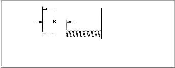
FIGURE 1
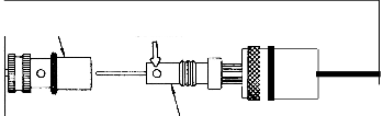
STEP 2. Slide UHF coupling nut onto cable with knurled end toward cable end. Add adaptor until flush with end of outer conductor. See Figure 2. Soft solder adapter to outer conductor. Use soldering iron or gun and rosin core solder. Avoid excessive heat. Keep inner conductor centered. Apply heat to adaptor to draw solder into hole. Wipe away excess solder and cool connection with damp cloth. Clean connection with garnet cloth. Do not use emery cloth or steel wool.
INNER CONNECTOR
![]()
FIGURE 2
SOFT SOLDER
ADAPTOR
COUPLING NUT
Andrew Corporation 10500 W. 153rd St. Andrew Antennas Andrew Antenas Umitada
Orland Park, IL U.S.A. 60462 Lochgelly, Fife, Great Britain Sorocaba, SP. Brazil
Antennas Andrew S.A.R.L Andrew GmbH
Buc, France Munich. West Germany
Andrew Antenna Company ltd. Whitby, Ontario, Canada
Andrew Antennas Antenas de Transmisi6n S.A de C.V Andrew Corporation
Campbellfield, Victoria, Australia Mexico, D.F. Mexico Tokyo, Japan
Andrew S.R.L Milan, Italy
6/83
PRINTED
IN U.S.A.
STEP 3. Screw UHF inner connector firmly onto adaptor. Soft solder connector to adaptor and to inner conductor as shown in Figure 3. Clean connec tion. Screw coupling nut bnto inner connector until nut spins freely.![]()
STEP 4. Slide Type N, BNC or TNC adaptor onto cable until flush with end of outer conductor. See Figure 4. Soft solder adaptor to outer conductor. Slip inner connector onto inner conductor until it bottoms against inner conductor. Check reference "C" dimension in table. Soft solder inner connector to inner conductor.
INNER CONNECTOR
SOFT SOLDER
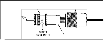
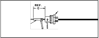
FIGURE 3
INNER
CONNECTOR SOFT SOLDER
COUPLING NUT
ADAPTOR
ADAPTOR
FIGURE 4
STEP 5. Screw Type N, BNC, or TNC coupling nut onto adaptor as shown in Figure 5. Tighten connec tion with wrenches. Turn coupling nut only; do not turn adaptor. Correct gap between coupling nut and adaptor after tightening should be approximately
3/32 in. (2 mm).
COUPLING NUT
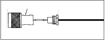

FIGURE 5
![]()
