Radar Definitions
"A",
"B",
"C",
"D",
"E",
"F",
"G",
"H",
"I",
"J",
"K",
"L",
"M",
"N",
"O",
"P",
"Q",
"R",
"S",
"T",
"U",
"V",
"W",
"X",
"Y",
"Z"

Twinax Connector Dimensions
Twinaxial Connector: [Twin-axial] A Twinax connector is a 50
ohm connector, similar to a Coax Connector, but dual pinned instead of a
signal pin. A twin-ax connector may be threaded or use a jamnut, as
shown above, for mating. The main application of Twinax connectors is on
components and cables used in RF systems.
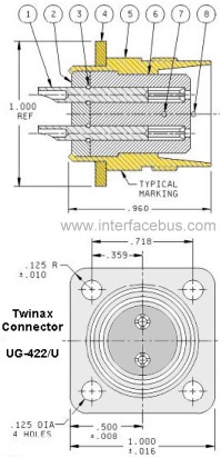
A Bulk-Head or Chassis Mount style Twinax Connector is shown in the
graphic. Note the dimensions for the chassis mounting hole is also
provided. Also that only one side of the connector is a cable interface,
the opposite end is a solder cup connection.
Three additional views are shown below including Twinax cable, Twinax Cable Flange Mount, and a Solder-cup Twinax connector.
Of course Twinax connectors come in a variety of styles: Wall-plate
Mount [Panel Mount]; Female To Female, T connector Female / Female /
Female, and 100 Ohm, Twinax Terminator to name just a few.
Twinax Connector Cable Termination
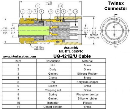
The drawing above is a cable terminating Twinaxial connector; also
called a Free-floating cable-end. The table provides the call-outs for
the individual components used in the construction.
MIL-DTL-3655/1; Connector, Plug, Electrical, Class I (Coaxial, Series Twin), Type UG-421B/U
Type M3655/1-0421 electrical connector is designed for use with radio frequency cable M17/15-RG22
Twinax Connector Cable Termination
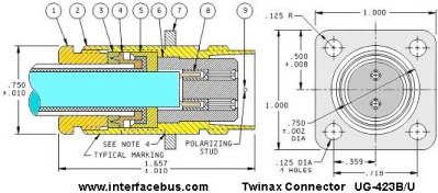
The twinax connector shown above is similar to the previous cable
termination style, but this example is a flange-mount, or panel mount
style. The relevant military standard is provided for reference.
MIL-DTL-3655/3; Connector, Receptacle, Electrical, Class I (Coaxial, Series Twin) Type UG-423B/U
Type M3655/3-0423 electrical connector is designed for use with radio frequency cable M17/15-RG22.
The connector in the lower right corner is an example of a solder-cut
termination, per the DOD standard listed. The solder-cup termination
allows the wire to be soldered to the connector, making a mechanical
connection.
MIL-DTL-3655/2; Connector, Receptacle, Electrical, Class I (Coaxial, Series Twin) Type UG-422/U
Type M3655/2-0422 electrical connector is designed for use with receptacle shield M3655/11-0106
The Twinax connector or Twinax cable is comprised of two inner
conductors which normally carries the signals surrounded by an outer
conductor [normally ground]. A Twinax Cable/Connector is used with a
differential signaling circuits and normally used with 78 ohm or 95 ohm
twin conductor cables [Twinax cables].
One of the interface buses that could use a Twinax connector is the MIL-STD-1553
bus. In addition there are also a number of interface buses that only
specify the electrical interface with out regard to the mechanical
interface, or connector. So there are a number of other differential
standards a Twinax connector could be used on. Because a Twinax coax
connector uses two axial leads surrounded by a shielded conductor a
twinax connector could be used with many differential cable interfaces.

Twinax Double Shielded Cable
A similar connector that only uses one conductor surrounded by a cable shield could be either a BNC Connector or SMA Connector. In almost all cases the cable shield is grounded when used with a BNC or SMA connector.
Note that a twinax connector or twinax cable has nothing to do with the cable having a shield or not, or how many shields the cable might have. Now the fact that the cable does have a shield is important to the electrical characteristics, but has nothing to do with the connector type. In addition, the number of metal braids used by a cable effects performance or aids in EMI shielding, but again does not directly relate to a Twinaxial connector.