

While I did salvage the lights in the last part, that was not all! There were also downlight transformers and luminaires to be salvaged too. Using a similar strategy to the last, I decided to salvage one of each sort to look at (and play with).
iGuzzini Tiltable Gimbal Fitting

All of the lamps removed from the lecture room were probably used to light the edges of the room and were installed using iGuzzini fittings which featured an one-axis gimbal, meaning that it could be either mounted with the beam pointing straight down, or tilted around to face a wall. The purpose of the fitting is to hold the lamp safely, make the electrical connections and dissipate the heat as necessary.

To that end, the bi-pin connection at the rear is made by a firm “wiper” based connection, and the front seems to be covered in a mylar insulation.

The rear of the connector uses a ceramic block to handle the heat, screwed to the aluminium frame with a few fins to keep the temperature limited. This is connected to silicone wiring of a short length, which is then joined to ‘regular’ cable using a terminal connector block. Of course, being fitted for many years, many of these had some corrosion and lots of dust on them.
ATCO LVL24A-2 Transformer

The oldest transformer in pile seems to be this locally-manufactured ATCO LVL24A-2. This one features a fixed input lead which cannot be replaced, and is terminated in a regular two-pin GPO plug. This transformer is rated for 12v AC output at 4A (for a total of 48w), and has a 23A short circuit current. This particular one is “safety isolating” by nature of the insulated separated windings, meaning the output is considered SELV.

All of them seem to have been operated long enough that the heat has caused the potting compound, used to mechanically secure the transformer plates, to crack. This looks bad cosmetically, but is unlikely to affect the performance of the transformer itself.
ATCO TM50A-2 Transformer

The next transformer, age wise, seems to be another locally produced unit. There seems to be a bit of a change to the design, with replaceable input wiring to terminal connector block underneath the hinged cover on the left. The transformer seems to be made for 11.4v output instead, with the lower output voltage resulting in slightly longer lamp life but at the cost of reduced output. The short circuit current seems to have been slightly reduced accordingly.
Unlike the above unit, this unit is slightly smaller and fully enclosed in black plastic without visible potting in the rear.

I’m not sure what this marking is, but I assume this could mean that this was made in week 39 of 1997. Lets just say that a regular iron-core transformer isn’t anything particularly special, so I tried to take it apart. Prying at the bottom released the plastic cover plate, which revealed a metal-base, and a potted nightmare. Underneath the plastic, the transformer was potted into the plastic case. It took some heavy prying to get the core out.

Not really worth it, I’d say, but you can see that the left white wire is used to “series up” the thermal fuse to the input primary, so as to cut power permanently to the transformer if it were to overheat.
ATCO STE50A-2 Transformer

It seems this one is even newer, with a slightly more slim design and cable entry/exit all on the same side with push down retention clips. It’s still a regular magnetic transformer, but the casing has gotten a little more intelligent – as it raises itself up off the surface it is mounted on for some additional cooling.

OSRAM ET-REDBACK 60VA/230-240 20-60W Electronic Transformer

Now we get to the really exciting part. All the transformers above were all “heavy” magnetic transformers which give you roughly 12v AC at 50Hz on the output (as you put in 240v 50Hz in the primary). This unit is different – it’s compact, and it’s very light, as it’s an electronic transformer. An electronic transformer is like a switchmode power supply, but since this one is intended for lighting purposes, the output waveform and voltage isn’t as tightly regulated or specified.
There weren’t many of these units in the pile, which means that it’s likely a later install or a replacement for previously failed transformers.
 This
unit seems to support dimming by leading/trailing edge control, a high
power factor of 0.95 and is double-insulated with SELV output. The
output, for a lamp, is rated at 11.5V AC, with a 2m maximum cable rating
(maybe for RFI reasons). Interestingly, the cable cap also features two
different holes which act as cable retainers for different cable
thicknesses.
This
unit seems to support dimming by leading/trailing edge control, a high
power factor of 0.95 and is double-insulated with SELV output. The
output, for a lamp, is rated at 11.5V AC, with a 2m maximum cable rating
(maybe for RFI reasons). Interestingly, the cable cap also features two
different holes which act as cable retainers for different cable
thicknesses.
To disassemble it, you merely have to pry at the bottom plastic tray to release it from the rest of the frame.

The main PCB is very small, and doesn’t have that many components.

You can see the input seems to pass through a large inductor or isolating transformer to reduce the RFI generated by this switching unit. There is a series thermal fuse on one of the heatsinks, with insulated wires reaching back into the PCB.There is also a regular fuse, covered in heatshrink to ensure no explosions in case of catastrophic failure.

The output transformer can be seen to be toroidal, which is efficient, but is made specially with a plastic cover to insulate primary from secondary in addition to the enameled copper wire. The feedback transformer is also separate and insulated from the main toroid. This is necessary to fulfill the requirements for double-insulation and SELV.

The underside shows a large gap between primary and secondary, with solder resist all over. Four surface mount diodes seem to form a full wave bridge rectifier for the input. A few assorted resistors and capacitors are also scattered on this side.
Electronic Transformer Output
This was the first electronic transformer I’ve come to own, so measuring its output was definitely of interest to me. So, I decided to power it up without any load on the output and see what came out.

Surprisingly, unloaded, the transformer didn’t give out anything like what I would imagine. It peaked over 23v positive over ground, and its AC RMS value was only 3.2v. It seems that the electronic transformer cannot operate below a certain amount of load which explains why replacing lower-powered single LED globes on some transformers just won’t work. The other thing is that the voltage regulation seems to contain high peaks, and lots of ripples, which can be stressful on LED globes – especially with those for poor regulation, as that can force excessive current peaks through the emitters.
The 50Hz seems to be existent in the output, so it seems that no work has been done to filter this out, and it becomes an advertising “feature” as being compatible with dimming, as the output will be duty-cycle modulated for dimming purposes.

Looking at the “ringy” pulse-train output, it seems to have a frequency of 3.54khz when unloaded.
I suppose none of this makes good sense when operating unloaded, so I threw in a regular 50w halogen downlight to see what its normal operating condition looks like.

The ballast seems to perform much more regularly, with a “flattened” top waveform that seems to correspond with the flattened top AC waveform that’s common here. It seems the transformer doesn’t operate below certain AC voltages resulting in “dead time” near the zero crossings of the AC input waveform. The average output voltage AC RMS is 11.76v, which is as expected.
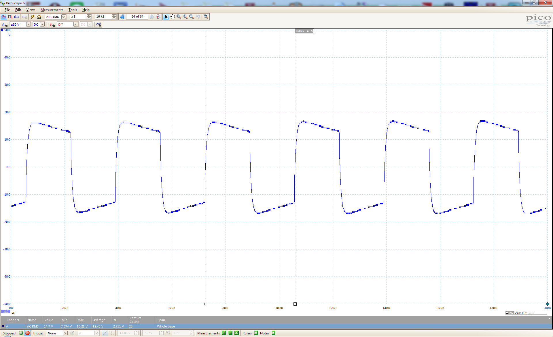
The ballast seems to put out a roughly square wave voltage at 29.84khz which is actually a pretty high frequency, so maybe some lamps might not have fast enough diodes (due to recovery time) on the input stage to properly rectify the voltage coming out of these electronic transformers which may result in energy waste and diode overheating.
Putting on the Philips 10W lamp seemed to have it operate successfully.

The voltage delivered was 12.05v AC RMS, which seems quite suitable for the globe.

However, the peak to peak average is 40.8v, so it has to deal with about 20v “peaks”, when designed for 12v operation.


The ripple seems to be comprised of two components – a larger square wave component at 60.85khz and a smaller square wave component superimposed at 344.8khz. That’s pretty rough on the lamps, and could be a cause of RFI.

A look at the voltage spectrum seems to show quite a few spikes above the noise up to about 4Mhz, which isn’t entirely surprising. Shortwave listeners and HF DXers generally don’t like anything with switching supplies because of the inevitability of this due to the harsh switching waveforms.
Conclusion
Rather surprisingly, all of these various LED globes and transformers were salvaged from a single lecture theatre. It’s very surprising to see this many different models used, all attached to the same gimballed light fitting. It’s the first electronic transformer I’ve actually come to use, and its behaviour is quite interesting – its output is actually pretty lousy. But I suppose it is lighter, and potentially more efficient than an iron based transformer. It explains why not all LED bulbs are suitable for use with electronic transformers though.


Pingback: Teardown & Test: Nelson Cougar 60 Electronic Downlight Transformer | Gough's Tech Zone
Osram documents say the Redback is compatible with at least Osram MR16 LEDmodules. I thought pretty much all LEDs run on 2-5V, so LED globe modules have voltage regulation circuitry and presumably aren’t all that fussy about the quality of input.
Hi Gough
I live in a complex of 300 apartments in Melbourne’s eastern suburbs. They were first occupied in 2010 so only 6 years old. I do a bit of handyman work within the complex and regularly get odd jobs thrown at me by my neighbor who is a real estate agent who has a port folio of about 30 rental apartments here.
All apartments are fitted with LED down lights powered by Osram ET-Redback 60VA /230-240 V transformers.
I reckon I’ve replaced at least 50 of the transformers since the apartments were built! Looking at Osram’s website today, I then read your blog about transformers you salvaged from a tear down with particular interest in these Osram trannies.
I’m a mechanical engineer so a lot of your electronic jargon went over my head. However I think you highlighted that these trannies need to have adequate loading to operate efficiently. Does this mean that 50W globes are preferable to 35 W? You also noted a fuse on the primary. Do you think it’s worth checking fuses on trannies I’ve replaced? New trannies cost <$10 so the failed ones are really throwaways.
My interest is understanding why the transformers are failing in such quantity. A suspicion I also have is that we get voltage spikes in the complex as there is a shopping centre below with fairly high kW connected loads on chillers and HVAC systems.
I'd appreciate your comments on the tranny failures.
Thanks
Bruce Golder
Generally, electronic transformers are pretty bulletproof and aren’t highly sensitive to the power quality as long as it’s roughly within voltage range. If you’ve got nothing to lose tearing down the transformers, you can try looking inside to see for obvious failures. Overheating is probably the main cause of failure, taking its toll on the capacitors – installing them into ceiling cavities too close to the globe, unventilated, or running for extreme hours (e.g. continuous), being dimmed (which produces harmonics from the hard-switched waveform which can be harder on the transformer) or switched too frequently (as this takes a toll on the soft-start circuitry). It’s important to realize that many of these units are not designed to last forever, and while not directly specified, many electronic products have a design life of about 5 years.
If you find that the fuse has blown, then indeed, something catastrophically bad may have happened. In which case, maybe you are correct in thinking that transient spikes are your issue as it may have blown the transistors on the transformer itself causing it to go short circuited and hence blow the fuse. However, it’s not possible to rule out generalized component failure due to exceeding design lifetime. In any case, it’s not advisable to blindly replace fuses, even if the unit might appear to work for a while as it may also have a fault which manifests itself only under certain conditions, and can represent a safety issue if the wrong rating is used. Further to that, other common causes can be failure in solder joints due to expansion/contraction, infestation by vermin (although not that likely), being overcome by dampness/humidity. On the whole, my impression was that ET Redbacks were pretty reliable and preferred by tradespeople – although your experience seems to suggest otherwise.
The ET Redback 60VA models can handle all loads from 20-60W in general, so there’s no big issue with running 35W globes as mandated by recent energy efficiency laws. Running low power LEDs seem to work, but may end up operating the transformer in a region below its design resulting in noise, unsteady output or stress on the transformer and the globe (e.g. spiky voltage output).
New electronic transformers are cheap and moderately efficient, but on the whole, they have complexity and component lifetimes which differ from the old “iron” transformers which would tolerate almost every condition.
– Gough
Pingback: Failed: Click LTMR5W3K 5W LED MR16-Replacement Globe | Gough's Tech Zone
I have a TM50A-2 ballast which is currently powering 2 halogen bulbs; which I want to swap out for more energy efficient LED bulbs (all non-dimmable).
I’ve read that some transformers aren’t compatible with LED bulbs due to their low load compared to the halogens, therefore in a LED conversion, these transformers would need to be swapped out for one that is compatible with LED bulbs.
Do you have any guidance on how to know which transformers can handle LED bulbs and which can’t? I have read that the actual core wound transformers would have no problems with powering either halogen or LED (in which case I believe I can use my TM50A-2 with LED bulbs no problem), and that microcontroller style ballasts are the ones that are affected (in all cases or just some??). Is that right?
I have a bit of an electronics background so I’d love to understand how this works in more detail… if you can clarify that would be great – Thanks!
Old fashioned iron-core transformers are very basic devices and, for the most part, faithfully reproduce the input AC at a smaller voltage on the secondary. Because it has no “smarts”, it has very little to go wrong and will produce 50Hz AC on the output, voltage varying slightly depending on load. This is the default waveform that most LED retrofit globes can most easily handle, as there are no “fast” rise/fall times (sinusoids are smooth and 50Hz is rather “leisurely”).
The light-weight electronic ballasts work through having the mains switched (chopped) at high frequency using TRIACs and the like. The result of this is an output that oscillates at close to 50-100kHz (1000-2000 times faster than the mains) and is hard “chopped” resembling a square wave riding inside a sinusoidal envelope. This makes the circuitry cheaper, enables the use of light-weight transformers and minimises waste heat, but also produces a waveform that can be harsh to rectify and feed into an electronic current driver, such as that of the LED retrofit globes. Some globes, hence, handle this issue better than others. Further to this, the ballast oscillator’s stability and waveform partially depends on the load that is on the output – that’s why under a certain load, they tend to be unstable as the TRIACs may not latch on with insufficient current. It is for a similar reason that old-fashioned wall dimmers also had a minimum load requirement – below this load, you would get flicker or instability in the light level and similarly, such an effect can manifest with electronic transformers used with LED globes along with some level of audible noise (buzzing/clicking/chirping). Sometimes you can get around this by “loading” the output by running a few more globes in parallel, but some other electronic ballasts just will not cooperate as the LED globes have a different voltage/current characteristic.
– Gough
Hi I have a transformer SLF5 777 035 close to the one you have on the board. I can’t find anything on it and would like to test it. What type is it? How can I test it with multimeter and can I test it on board? Thank you
It’s easiest just to feel the weight. If it feels like a brick – it’s a conventional iron core transformer. If it’s like and tinny-cased, then it’s probably electronic. If you hear high pitched hissing or buzzing in operation, then it is likely to be electronic.
Testing with a multimeter is inconclusive most of the time as the outputs are both AC. However, electronic transformers have much more higher frequency components and harmonics and are more likely to read incorrect voltages especially under-loaded on many multimeters.
The best proof is to find the manufacturers’ information or to open the unit up and inspect it yourself. Sometimes the printing also gives you a clue, especially if it uses the word “electronic” anywhere on the printing.
– Gough
It’s exactly like the one on the pic except mine finishes with 035. No manufacturer written on it. It’s on a non led 13w fluorescent t5 ministrip fixture with two mini pcb’s on each end no casing like usual ballast. I tested the switch, wires, tube and sockets fir continuity they are fine. Nothing looks damage or burnt. Capacitors are not bulged but I haven’t unsoldered anything yet. The light stopped lighting up a few times and worked by turning off and on once more. Then worked for two weeks and then stopped all together. Tried new tube also. I was told it might be the transformer from an electronics forum user who saw the pics. I do have some very light darkening on the plastic back plate under the pcb side where the transformer is but not on the underside of the pcb though. What’s your take on it? Everything looks brand new on this fixture.
Thank you!
The unit with the component marked SLF5 777 132 is an electronic MR16 downlight transformer. It is not for use with fluorescent tubes. I suspect perhaps your unit uses a transformer wound from the same company as the Osram Redback electronic MR16 transformer, but the design is probably completely different.
It sounds like an electronic ballast – there are a long list of possible causes including failing capacitors (which might also cause stability issues especially if it is a bootstrap capacitor for an IC), leaky transistors (which lead to blown fusible resistors/fuses later), transformer shorts, overheating, hairline cracks in PCB/solder joints. You will have to take a closer look at the circuitry and how it works to get an understanding of the issue, but most of the time, replacing the module is probably quicker and cheaper.
– Gough