
The DRV8825 stepper motor driver carrier is a breakout board for TI’s DRV8825 microstepping bipolar stepper motor driver. The module has a pinout and interface that are nearly identical to those of our A4988 stepper motor driver carriers, so it can be used as a higher-performance drop-in replacement for those boards in many applications. The DRV8825 features adjustable current limiting, overcurrent and overtemperature protection, and six microstep resolutions (down to 1/32-step). It operates from 8.2 to 45 V and can deliver up to approximately 1.5 A per phase without a heat sink or forced air flow (rated for up to 2.2 A per coil with sufficient additional cooling). Features:
Documents:Included hardware:The DRV8825 stepper motor driver carrier ships with one 1×16-pin breakaway 0.1" male header. The headers can be soldered in for use with solderless breadboards or 0.1" female connectors. You can also solder your motor leads and other connections directly to the board. Power connections:The driver requires a motor supply voltage of 8.2 to 45 V to be connected across VMOT and GND. This supply should have appropriate decoupling capacitors close to the board, and they should be capable of delivering the expected currents. Warning: This carrier board uses low-ESR ceramic capacitors, which makes it susceptible to destructive LC voltage spikes, especially when using power leads longer than a few inches. Under the right conditions, these spikes can exceed the 45 V maximum voltage rating for the DRV8825 and permanently damage the board, even when the motor supply voltage is as low as 12 V. One way to protect the driver from such spikes is to put a large (at least 47 µF) electrolytic capacitor across motor power (VMOT) and ground somewhere close to the board. Motor connections:Four, six, and eight-wire stepper motors can be driven by the DRV8825 if they are properly connected; a FAQ answer explains the proper wirings in detail. Warning: Connecting or disconnecting a stepper motor while the driver is powered can destroy the driver. (More generally, rewiring anything while it is powered is asking for trouble.) Step (and microstep) size:Stepper motors typically have a step size specification (e.g. 1.8° or 200 steps per revolution), which applies to full steps. A microstepping driver such as the DRV8825 allows higher resolutions by allowing intermediate step locations, which are achieved by energizing the coils with intermediate current levels. For instance, driving a motor in quarter-step mode will give the 200-step-per-revolution motor 800 microsteps per revolution by using four different current levels. The resolution (step size) selector inputs (MODE0, MODE1, and MODE2) enable selection from the six step resolutions according to the table below. All three selector inputs have internal 100kΩ pull-down resistors, so leaving these three microstep selection pins disconnected results in full-step mode. For the microstep modes to function correctly, the current limit must be set low enough (see below) so that current limiting gets engaged. Otherwise, the intermediate current levels will not be correctly maintained, and the motor will skip microsteps.
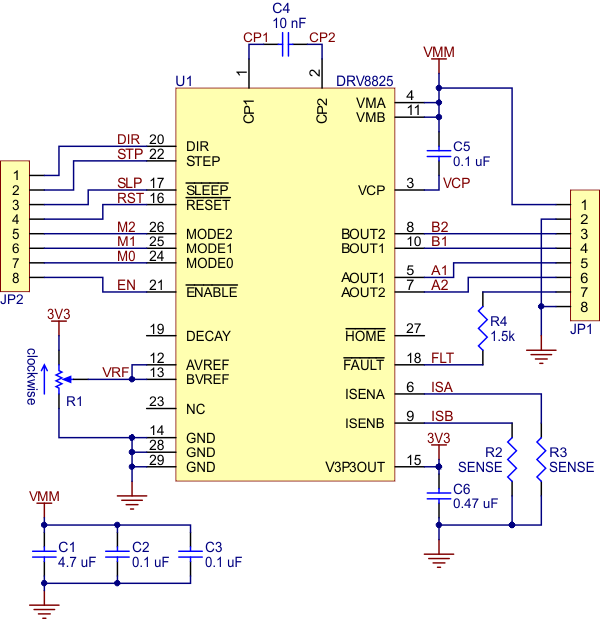
Control inputs:Each pulse to the STEP input corresponds to one microstep of the stepper motor in the direction selected by the DIR pin. These inputs are both pulled low by default through internal 100kΩ pull-down resistors. If you just want rotation in a single direction, you can leave DIR disconnected. The chip has three different inputs for controlling its power states: RESET, SLEEP, and ENBL. For details about these power states, see the datasheet. Please note that the SLEEP pin is pulled low by default through a 1MΩ pull-down resistor, and the RESET and ENBL pins are both pulled low by default through internal 100kΩ pull-down resistors. This means that RESET and SLEEP will be preventing the driver from operating if left disconnected. Both of these pins must be pulled high to enable the driver (they can be connected directly to a logic “high” voltage between 2.2 and 5.25 V, or they can be dynamically controlled via connections to digital outputs of an MCU). The default state of the ENBL pin is to enable the driver, so this pin can be left disconnected. The DRV8825 also features a FAULT output that drives low whenever the H-bridge FETs are disabled as the result of over-current protection or thermal shutdown. Otherwise, the pin is floating, so you will need to use a pull-up resistor to give it a default high state if you want to use this pin. Note that there is a 1.5k protection resistor in series with the pin that you should take into account when selecting your pull-up resistor (i.e. it should probably be at least 10k). This 1.5k series resistor means it is safe to connect this pin to a logic high voltage, as might happen if you use this board in a system designed for the pin-compatible A4988 carrier. Current limiting:To achieve high step rates, the motor supply is typically much higher than would be permissible without active current limiting. For instance, a typical stepper motor might have a maximum current rating of 1 A with a 5 Ω coil resistance, which would indicate a maximum motor supply of 5 V. Using such a motor with 12 V would allow higher step rates, but the current must actively be limited to under 1 A to prevent damage to the motor. The DRV8825 supports such active current limiting, and the trimmer potentiometer on the board can be used to set the current limit. One way to set the current limit is to put the driver into full-step mode and to measure the current running through a single motor coil without clocking the STEP input. The measured current will be 0.7 times the current limit (since both coils are always on and limited to approximately 70% of the current limit setting in full-step mode). Another way to set the current limit is to measure the voltage on the “ref” pin and to calculate the resulting current limit (the current sense resistors are 0.100 Ω). The ref pin voltage is accessible on a via that is circled on the bottom silkscreen of the circuit board. The current limit relates to the reference voltage as follows: Current Limit = VREF * 2 So, for example, if the reference voltage is 0.5 V, the current limit is 1 A. As mentioned above, in full step mode, the current through the coils is limited to 70% of the current limit, so to get a full-step coil current of 1.5 A, the current limit should be 1.5 A/0.7=2.1 A, which corresponds to a VREF of 2.1 A/2=1.05 V. See the DRV8825 datasheet for more information. Note: The coil current can be very different from the power supply current, so you should not use the current measured at the power supply to set the current limit. The appropriate place to put your current meter is in series with one of your stepper motor coils. Power dissipation considerations:The DRV8825 driver IC has a maximum current rating of 2.5 A per coil, but the current sense resistors further limit the maximum current to 2.2 A, and the actual current you can deliver depends on how well you can keep the IC cool. The carrier’s printed circuit board is designed to draw heat out of the IC, but to supply more than approximately 1.5 A per coil, a heat sink or other cooling method is required. This product can get hot enough to burn you long before the chip overheats. Take care when handling this product and other components connected to it. Please note that measuring the current draw at the power supply will generally not provide an accurate measure of the coil current. Since the input voltage to the driver can be significantly higher than the coil voltage, the measured current on the power supply can be quite a bit lower than the coil current (the driver and coil basically act like a switching step-down power supply). Also, if the supply voltage is very high compared to what the motor needs to achieve the set current, the duty cycle will be very low, which also leads to significant differences between average and RMS currents. Additionally, please note that the coil current is a function of the set current limit, but it does not necessarily equal the current limit setting. For example, in full-step mode, the coil current is internally limited to 70% of the set maximum, so you would set the current limit to around 2.1 A to get a coil current of 1.5 A. Schematic diagram:
The SENSE resistors R2 and R3 are 0.100 Ω on this version of the DRV8825 carrier. Key differences between the DRV8825 and A4988The DRV8825 carrier was designed to be as similar to our A4988 stepper motor driver carriers as possible, and it can be used as a drop in replacement for the A4988 carrier in many applications because it shares the same size, pinout, and general control interface. There are a few differences between the two modules that should be noted, however:
|
||||||||||||||||||||||||||||||||||||||
Feature Comparison: |
||||||||||||||||||||||||||||||||||||||
Support: |
DRV8825 High Current Stepper Motor Driver Carrier
Compare product with:
| Copyright © 2001-2016 Ocean Controls | Phone: +61 3 9782 5882 | ABN: 22 061 932 027 |