Building a DC Drive for the Bridgeport Spindle
February, 2004 -- January, 2007.
 The primary power in a vertical milling machine is an electric motor
driving the spindle. In this project, I replaced the original 1-HP 3-phase 230
VAC electric spindle motor on a Bridgeport machine with a 3/4-HP DC drive motor.
By adapting surplus, high-quality components, I was able to implement the
superior characteristics of DC drive for less than the cost of the usual VFD
retrofit.
The primary power in a vertical milling machine is an electric motor
driving the spindle. In this project, I replaced the original 1-HP 3-phase 230
VAC electric spindle motor on a Bridgeport machine with a 3/4-HP DC drive motor.
By adapting surplus, high-quality components, I was able to implement the
superior characteristics of DC drive for less than the cost of the usual VFD
retrofit.
Benefits of DC drive include:
- Source power is 120 VAC single-phase house current instead of
industrial 3-phase service.
- Infinite variable-speed control of the motor.
- Full torque at lowest speeds without changing step-pulley belts.
- DC motor characteristics are better matched to task loads compared
to AC motors.
|
Of vital importance to the
small shop is that machines run off single-phase electric power. Larger machine
tools are almost always originally equipped with 3-phase AC motors. When running
such machines in a shop with only single-phase supply, the usual adaptation is
to install a "phase converter" or electronic variable-frequency drive (VFD),
neither of which is entirely satisfactory, and both of which involve some
expense and require some space. Phase converters are both inefficient in the use
of the electric power, and reduce the shaft power available from the motor.
VFD's are more modern devices designed as electronic charge pumps; most can run
off single-phase input power, with some inefficiency and derating of the maximum
converted power rating, although the motor can be fully supplied if an
over-rated VFD is employed. A VFD also provides a limited range of speed
control; the more sophisticated implementations offer programmable acceleration
and torque settings, and even computer interface and control. While the expense
of these converters is in the multiple $100s, they are cheaper than retrofitting
a DC motor and drive, so they are typically the practical solution.
DC motors and controls offer another solution to the power compatibility
problem, while offering distinct mechanical advantages compared to any method
involving stock AC motors:
- Torque and speed are controllable independently and over the entire
range from zero to maximum ratings (torque proportional to current
supplied, speed proportional to voltage). This is well-matched to
milling applications, where various speeds-and-feeds requirements
reflect back to the prime mover as motor speed and torque requirements.
- Peak and short-term delivered power can be multiples of the
continuous rating. This is also well-matched to milling applications,
where periods of heavy cutting intersperse with lighter cuts.
|
While a DC motor has a continuous horsepower
rating, it can deliver and sustain multiples of that horsepower, subject to heat
dissipation and mechanical limits. A 3/4 HP DC motor can replace a stock AC
motor rated from 1 to 2 HP. The DC motor control converts the AC input power to
a variable voltage and current-limited DC supply, typically through a chopped
MOSFET charge-pump and rectifier design. The DC controller may also have
settings for acceleration and deceleration rate, maximum torque, maximum
voltage, and jumpers for AC input voltage (120 vs 240 VAC).
For all their advantages, DC motors are not used much because both motors and
controls are expensive, and the brushed designs require periodic maintenance for
brush inspection and replacement. But it is primarly the cost of DC motors and
drives preventing their use in machine tools. However, in my experiments with DC
motors for servo control, I acquired a number of permanent magnet DC (PMDC)
motors and controllers at very low cost.
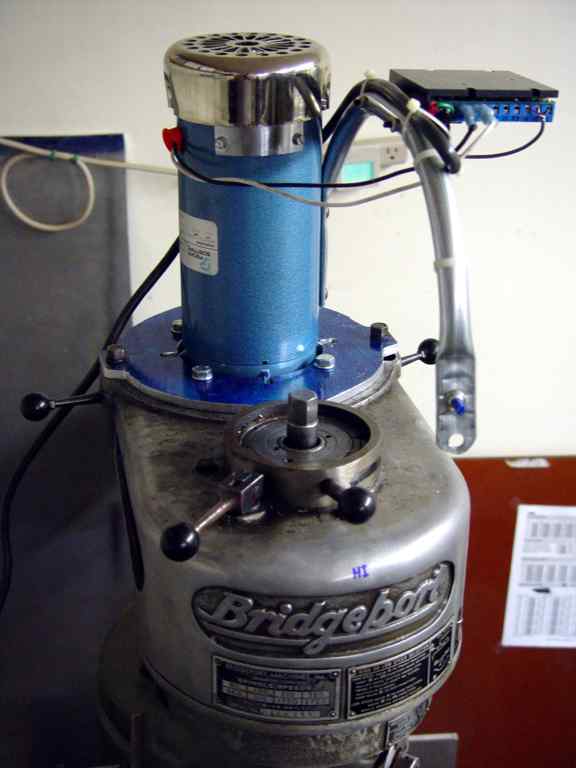
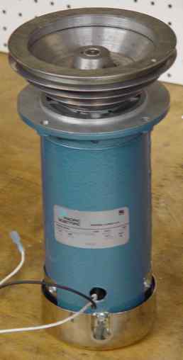
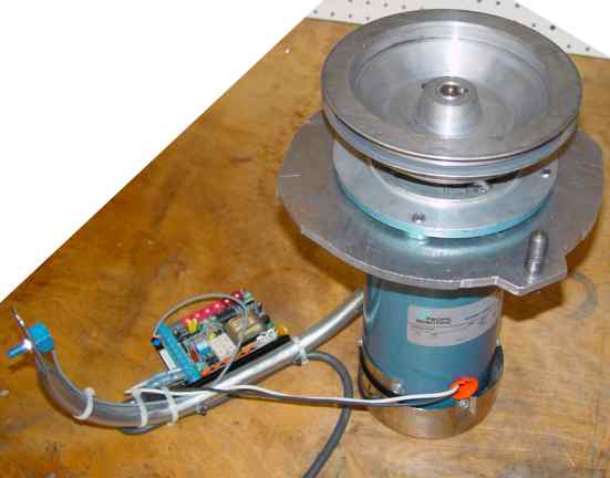
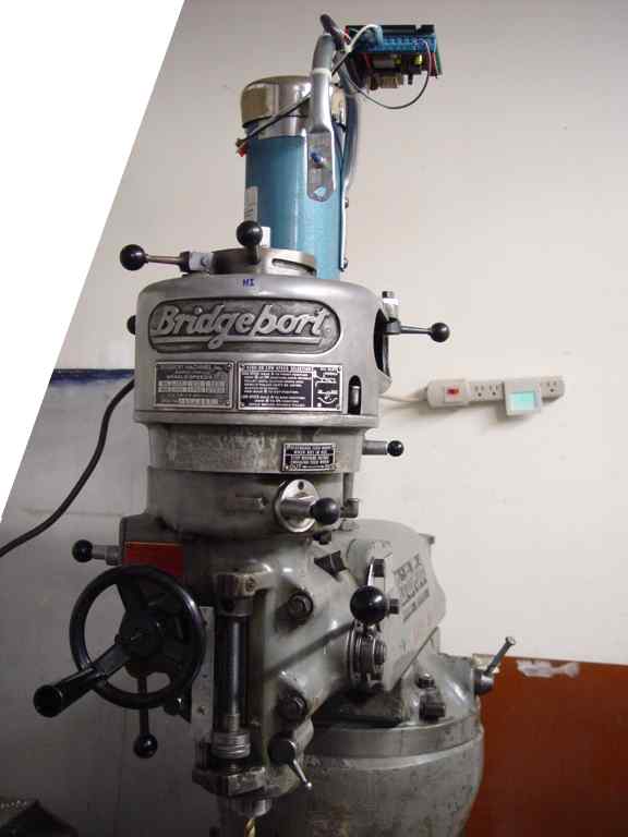
This photo shows the finished project, with the blue motor and blue adapter
plate installed on the Bridgeport milling machine. The 1970s-vintage machine is
equipped with a Bridgeport J-head, which originally had a 1-HP 3-phase "pancake"
motor installed where the DC motor is now installed. To mount the DC drive
controller and power connections, I bent and flattened some 1/2" thin-wall
electrical conduit (EMT) using a conduit bender and arbor press, and attached it
to the motor where the baseplate would attached with 5/16" screws. The flattened
end of the conduit at the front of the J-head holds the potentiometer which
controls the motor speed. The empty hole just below will hold a manual on-off
switch (for now I just use a socket strip) connected to the controller's
low-voltage start-stop signal; the planned CNC conversion will control the motor
directly. This is all up on top of the machine, over 6 feet high, where it is
out of the way of chips and materials.
Let's go through the steps involved in this project.
Acquiring the Motor and Controller
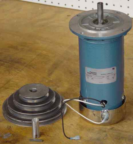
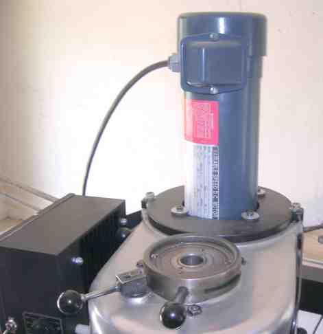
The motor I had available is shown
here, a Pacific Scientific 3/4 HP PMDC motor, model SRF3736-4243-7-56HC (mechanical drawing, 42 KB PDF
file). This is a NEMA-standard 56C motor, with a washdown housing
(total-enclosed fan-cooled, or TEFC, and able to sustain wet environments), but
minus the connection box and baseplate. The NEMA C-flange series of dimensions
is the most common type of motor face mount. NEMA 56C size indicates a
"C-flange" (also known as "C-face") mounting, that is, a face mounting plate
with threaded bolt holes on a bolt circle around the shaft, in this case, 3/8-16
bolts every 90 degrees around a 5.875" circle, with a 5/8" diameter shaft
projecting 2" from the shaft. While this motor runs about $500 new, I found this
new one for less than $50 on eBay. Also shown are the original cone pulley from
the Bridgeport machine, and a bushing and key to adapt the motor shaft size to
the pulley.
The controller (seen mounted on the conduit tube in the first photo) is a
single circuit board about 6-inches square and 1-inch high, with its own
aluminum heat sink. Controllers like this are typically about $300. This one
happens to be an Electrol model 790, likewise an eBay purchase for $75. It can
be jumpered for 120 or 240 VAC input, and configured with switches and
potentiometers for acceleration, deceleration, min/max speeds, torque limit, IR
feedback compensation, and 90 vs 180 VDC motors.
DC motors and controllers are standard industrial items widely available from
suppliers like Grainger. There are
cheaper controls available that provide only speed regulation that would be
suitable. If you were shopping for appropriate items, you would want to consider
an appropriate horsepower, and find a compatible (or at least adaptable) shaft
size and mounting configuration, such as the NEMA 56C size shown here.
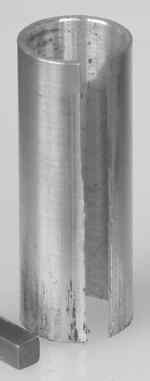
Adapting the Shaft Size
The original motor provided a 3/4" shaft with
3/16" keyway, on which was mounted a specific cone pulley (step pulley). The new
DC motor provides a 5/8" shaft and the same keyway. Rather than try to find this
same pulley with the smaller 5/8" shaft size, I machined a bushing to allow the
original pulley to fit the new motor shaft. This bushing is simply 3/4" (+0)
outside diameter and 5/8" (+0.002") inside diameter, turned on the lathe from
6061 aluminum. The length is 2" to cover the entire shaft length of the new
motor. I cut the 3/16" keyway on the mill-drill using side-milling on a 3/16"
end mill.
MSC sells a similar cone pulley in various shaft bore sizes. The 5/8" bore is
part number 00053843.
The 3/4" bore is part number 00053850.
These have stepped nominal OD sizes of 3, 4, 5, and 6 inches. The pitch
diameters are 2.7, 3.7, 4.7, and 5.7 respectively.
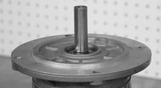
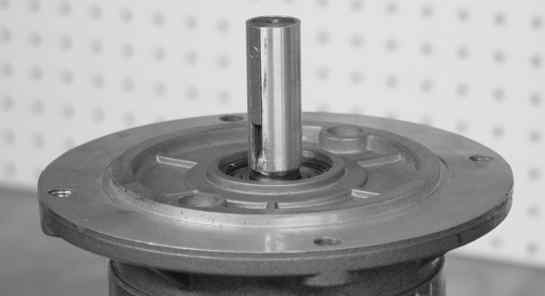
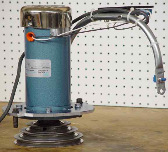
Mounting the Step Pulley
Here is the shaft end of the new motor in three
views. First, the bare shaft.
 Same motor shaft, with the bushing installed.
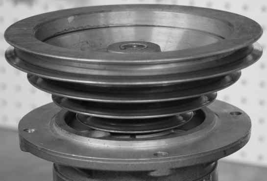 Same motor again, with the bushing and cone pulley installed.
 This is the completed motor assembly before mounting.
 Here is the drawing. Select the thumbnail at left to bring up
the detailed PDF version.
Here is the drawing. Select the thumbnail at left to bring up
the detailed PDF version.
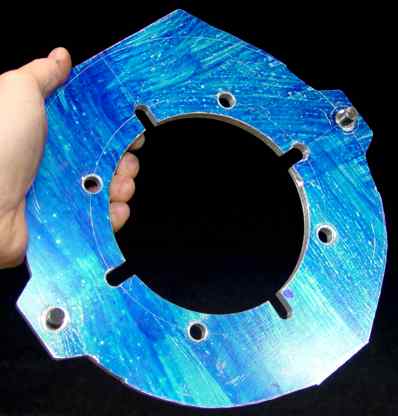
Machining the Adapter Plate
| If you don't care to make this adapter plate yourself, the completed
item, now fabricated on my CNC Bridgeport milling machine (instead of the
manual layout and machining described here), is available direct from me
for $250. The plate is supplied with a standard 3-inch center hole, and is
ready for you to drill for your motor's bolt-circle mounting holes.
Shipping is via USPS Priority Mail for an additional $10. USA addresses
only. Shipment is 1 week from receipt of your order and payment. |
|
|
The original Bridgeport "pancake" motors use a short, fat design that mounts
directly to the large opening in the J-head aluminum casement. The new motor is
relatively tall and skinny, and therefore requires a custom mounting plate to
adapt the face to the opening in the J-head, and to align the drive pulley to
the driven pulley. By making a lot of measurements and sketches, I came up with
this
design [drawing, 118 KB PDF file] for the adapter plate. See also the 3D model
[21 KB DWF file, requires the free Autodesk
DWF Viewer]. This started as a rough hand sketch [drawing, 22 KB
PDF file]. The plate is cut from 5/16" thick aluminum sheet, on which I painted
blue layout dye and scored layout axes and positions using a carbide scribe,
ruler, caliper points, and a compass. The mounting of this plate, and therefore
the center cutout, are rather unusual, because the axial alignment required that
the rear of the motor faceplate (instead of the front as usual) attach to the
adapter plate. The center cutout is therefore sized to pass the body of the
motor, with notches for clearance to the gussets reinforcing the motor
faceplate, and 4 holes for the 5.875" diameter bolt circle attachment of the
motor. The two "ears" at the edge of the adapter (shown with the original 1/2"
hold-down bolts from the old motor) attach the motor to the J-head. To make this
complex cutout, I wrote G-code by hand for the CNC mill-drill machine, which cut
and drilled the pattern using 1/4" and 3/8" end mills. I checked the G-code by
dry-running the paths on the machine, and watching that the tool path followed
the manual scribe marks. Hand-written G-code for a shape like this involves some
tricky trigonometry, and I had to make quite a few corrections to the code
before it was correct and ready to commit to metal. Aside from the ears, the
outside edge is only roughly cut on the band saw, since the mill-drill travel
was insufficient to reach the edges of the nearly 11 inches of diameter. I could
have done a neater job of CNC cutting the curves by re-clamping and
re-registering the work, but this was not worth the effort for a non-functional
aspect of a one-off part.
You may notice that the adapter plate mounts oddly onto the motor, being
bolted to the back side of the face flange, instead of normally on the front.
This was necessary to get the proper axial alignment of the motor to the machine
casement, such that the drive pulley lines up with the driven pulley. This
modified mounting successfully fit the random motor I happened to have to the
machine. A motor in a different power size might have had the proper alignment
and shaft size, or might have required a different adaptation. This is something
to plan carefully for when shopping for a motor.
Completing the Assembly
Here are some photos showing the completed
assembly before mounting on the machine.
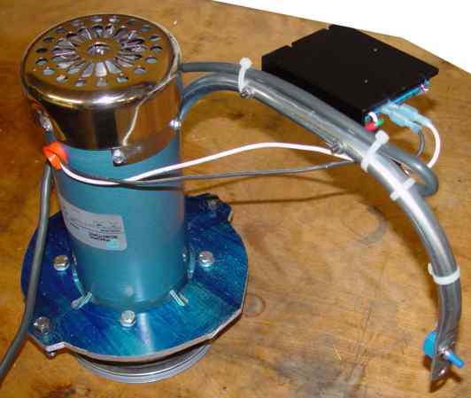
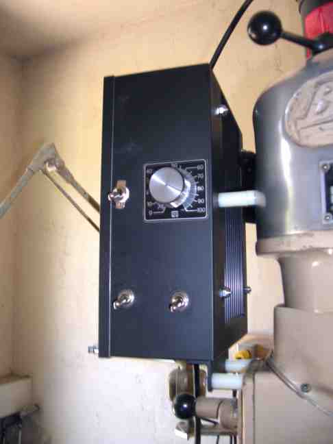
 This is the view from the operator's normal position of the
installed drive. I hope to make a proper enclosure for the control board, speed
dial, and on-off switch.
This is the view from the operator's normal position of the
installed drive. I hope to make a proper enclosure for the control board, speed
dial, and on-off switch.
The drive is a joy to operate, with the tiny dial giving complete control of
the motor speed from 0 to 1750 rpm. For routine work, I keep the pulley on the
third-highest step, disengage the backgear, and use the speed control dial to
set the proper speed for the application. By varying the step-pulley and
backgear combinations, I can further vary speed and torque with gear ratios in
various steps from about 1.6 down to 0.046. Since the motor develops about 3
ft-lb continuous torque (and a potential for some multiples of that), the
spindle can be geared down to a few rpm at over 65 ft-lbs, which translates to
several tons of force on the edge of a 1/2" cutter. Try that with your VFD!
Looked at the speed ratios another way, the stock motor specifies 1730 rpm at
60 Hz 3-phase power. The spindle speed table stamped on the head of the
Bridgeport machine says the spindle speeds for the four pulley steps are 660,
1115, 1750, and 2720 rpm. These are ratios of 0.382, 0.645, 1.01, and 1.57 from
the nominal 1730 rpm motor. Since I am using the 3rd step for general work, this
is more or less a 1:1 ratio of spindle to motor. The ratios given by Bridgeport
must include some significant belt slippage, since the pulleys are of obviously
different diameter.
How Others Have Done This
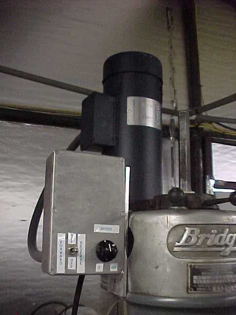
 Bob McKee kindly sent me photos of his DC drive retrofit. Bob used a
new 3/4 HP Electrol motor he found on eBay. He used a KBCC-R controller and
fabricated a box to house it, mounted on the left of the mill, replacing the
original forward-off-reverse switch for the original 3-phase motor. Bob reports
that he "wanted the reverse to perform dead spindle tapping; it works great. The
switches on the motor control box are: Top Left, Power on and off. Lower Left,
Machine on and off. Lower Right, Forward/Brake/Reverse. Upper Right, Speed
Control."
Bob McKee kindly sent me photos of his DC drive retrofit. Bob used a
new 3/4 HP Electrol motor he found on eBay. He used a KBCC-R controller and
fabricated a box to house it, mounted on the left of the mill, replacing the
original forward-off-reverse switch for the original 3-phase motor. Bob reports
that he "wanted the reverse to perform dead spindle tapping; it works great. The
switches on the motor control box are: Top Left, Power on and off. Lower Left,
Machine on and off. Lower Right, Forward/Brake/Reverse. Upper Right, Speed
Control."
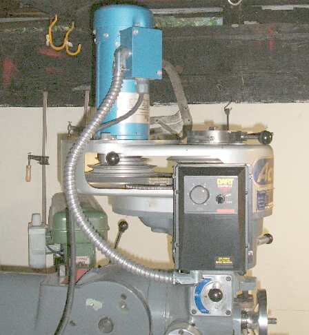 A fellow named Joe sent me this photo of his DC drive retrofit. He
used a 1 HP Pacific Scientific motor (new) and a Dart DC controller (new) from
eBay for a grand total of $110. His mill is an Acra make, which is an imported
Bridgeport copy, and which uses the step-pulley drive.
A fellow named Joe sent me this photo of his DC drive retrofit. He
used a 1 HP Pacific Scientific motor (new) and a Dart DC controller (new) from
eBay for a grand total of $110. His mill is an Acra make, which is an imported
Bridgeport copy, and which uses the step-pulley drive.
 John Horton wrote to say, "I made the plate from your drawing, The
motor is a 1.25 HP 180 volt from surpluscenter.com [part number 10-2213].
Controller is a Beel industries unit. Works great. It will not stall even on the
heaviest cuts." Suitable controllers available from surpluscenter.com look to be
the open-frame Minarik MM23001C (surpluscenter.com part number 11-2269)
or the encased and assembled (part number 11-2102).
John Horton wrote to say, "I made the plate from your drawing, The
motor is a 1.25 HP 180 volt from surpluscenter.com [part number 10-2213].
Controller is a Beel industries unit. Works great. It will not stall even on the
heaviest cuts." Suitable controllers available from surpluscenter.com look to be
the open-frame Minarik MM23001C (surpluscenter.com part number 11-2269)
or the encased and assembled (part number 11-2102).
Have a comment or question about my Bridgeport DC drive?
Email me
at:
mailto:kinch@truetex.com?subject=DC
Drive for Bridgeport
Richard J. Kinch
Back to Machine Shop page
Back to Home page