Water
Purification Water
Desalination Energy Demand
Crisis Water
for Poor Water From air

GCODE Introduction for Programmers
Here are a few notes I made while learning GCODE. It is written from the
perspective of a person who already knows a scripting languages.
I hope it helps. Let me know about any suggested changes at joe@xdobs.com or if you would like some help
extending our library for your project.
Most people do not need to learn GCODE because the normal CNC
process allows people to use CAD and CAM software to
generate the GCODE from their 3D CAD drawing. We encountered problems
with the normal process which encouraged us to write CNCUtil, a Ruby library
that directly produces the GCODE
GCODE is a
language that is so simple that you can learn the basics and do real work in a
few hours. Even the more sophisticated things are easy to understand.
GCODE is also one of the worst languages I have ever seen if you have to edit
large scripts. All the tools that software engineers use to manage complex
systems such as functional decomposition and encapsulation are missing.
Sophisticated GCODE scripts are quite often over 10,000 lines and if you have to
find one particular line to edit it can require scanning all 10,000 lines. The
simulators help but not nearly as much as real engineering tools do.
The reason I wrote our ruby scripting library CNCUtil to Automatically
generate GCODE from higher level specifications is that our projects where
simply too complex. We could not afford to to sit around writing 10,000 lines of
GCODE and then have to edit 3,000 of them to make a simple change. CNCUtil has
been quite successful so that 10,000 lines of GCODE can be generated from 10 to
15 lines of ruby script and if I change a dimension it is normally only a one
line code change. I often find it is faster to use CNCUtil that it was to draw
the part in CAD and then convert it to GCODE. CNCUtil also comes closer to
generating ideal GCODE. I also like CNCUtil because it automatically takes care
of most of the MATH which consumes a lot of the GCODE programming time.
I do not claim this tutorial is technically correct but it does work with
the EMC2 CAM driver software when hooked to a Xylotex controller board.
Coordinate Space
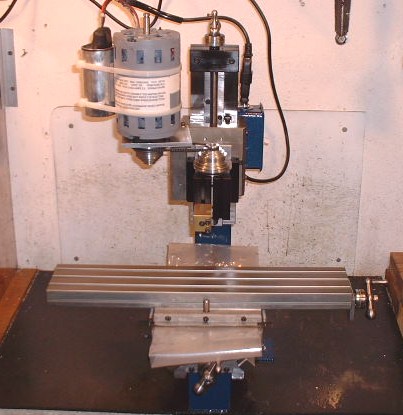 My mill is a Taig 2019 micro mill. It is one where the milling
head stays stationary on the X and Y axis while the table moves under the head.
The head moves up and down on the Z axis. This means that when the table
moves in one direction the stationary head is actually moving in the opposite
direction relative to the material
My mill is a Taig 2019 micro mill. It is one where the milling
head stays stationary on the X and Y axis while the table moves under the head.
The head moves up and down on the Z axis. This means that when the table
moves in one direction the stationary head is actually moving in the opposite
direction relative to the material
It is important to logically think about the head movement relative to the
work piece. It is easy to get table movement mixed in and it will cause you to
mix up directions every time.
In otherwords pretend that the material was always stationary and that the
head is the item moving.
Always think in head movement relative to the material even if
it is the table or part moving.
Increasing X will move milling head Right by moving the table left. On my
Taig this moves the table to the left. Moving from the extreme right to the
extreme left this mill allows 14.5 inches of movement. I always set mine up so
that the table marked dead center is X = 0 so that it can move from a X of -7.25
to X+7.25. I try to never use the to allow some room just in case the alignment
is off. On larger pieces I use the plus and minus axis but on smaller pieces I
tend to work always on the + side.
A decrease in x will move milling head left on my Taig this moves the table
towards the back or towards the main support column. From it's most extreme
forward position it can move a maximum of 4.5 inches but about 0.6 inches of
this is blocked by the bottom of the Z axis gearing which means that if you are
milling anything over 1 inch thick you really only have 4 inches of movement. I
align mine so that Y is set to 0 at the forward edge of the work piece which
allows quick and dirty alignment check by running back and forth on the X axis.
I normally configure mine so that I can move up to 4.0 inche on the Y axis and
back to -0.5 but generally always work in the + coordinate space.
Decreasing y will move the head back. It actually moves the table towards me
if I am standing in front of the mill which moves the part away from the wall
but when looked at it relative to the material it is logically moving the head
toward the wall which is opposite the table direction.
Origin of Movement
All milling operations are done relative to X=0, Y=0, Z=0. The EMC2 software
allows you to manually move the head and then set each axis to zero. This means
your code can be designed to work from any corner of the piece or the center if
needed. In practice it is generally a good rule to use the one corner as the of
the work material as the 0. There are times when it makes more sense to start in
the center for one or more axis. On our parabola project
the front edge on the Y axis is 0 but the center of the 15 inch work piece is 0
on the Z axis.
Absolute Coordinates
By default all coordinates are in an absolute grid space relative to
X=0,Y=0,Z=0, It is possible to change the current state and make movements
relative but we normally leave things in the absolute space as it is easier to
keep track of. If I was doing a lot of manual GCODE instead of using our library
I would probably use the relative space more often.
Note: There is an option in most controller software to reverse the
directions of X,Y,Z and A axis movements. I am using the defaults with my
Xylotex controller board and EMC2. You will want to test your movement to make
sure it is the same.
An example program:
        %
       (required)(example gcode box)
        G00 Z0.5 (raise bit above work)
        G00 X0 Y0 (move bit to starting position)
        G01 Z -0.5 F8 (lower bit = inch to allow milling)
        G01 X1 Y0 F8 (move to top right corner)
        G01 X1 Y1 F8 (move to bottom right corner)
        G01 X0 Y1 F8 (move to bottom left corner)
        % (required)
This simple example illustrates the how to mill a simple rectangle which has
one inch side long sides. As you can see the programmer is responsible for
keeping track of current location and walking around perimeter. This has only
milled a rectangular line = inch deep. Milling a pocket would require decreasing
the radius by a cutting increment and doing it over and over again until you
meet in the center.
Editing
This seems to be an often confused issue with GCODE because there are custom
GCODE editors available. GCODE is a simple text file that can be edited with any
text editor such as Notepad which is built in to windows or Kwrite and VI which
are built in to Linux.
The GCODE specific editors can make the task a little easier because they
remember some of the syntax but I dont find them worth the hassle because they
are neither as fast or as feature rich as free programming editors such as
Anyedit at http://www.anyedit.org/
I seldom have to write GCODE directly because I use our Ruby library but when
I do I use EditPlusfrom
http://www.editplus.com/ because it is easy to produce a syntax file for
EditPlus that show the GCODE in color.
Testing / Emulating
It is a really good idea test gcode before risking your expensive cnc bits or
material. It is very easy to miss single command that causes the bit to make a
cut right where you do not want it. I currently use> Microtech CNC Simulator from
http://www.cncsimulator.com/ but there are many available and are documented in
our CNC overview document. and in the links portion of our CNC site.
The final test should always be ran with the head raised on the milling
machine it self. This allows you to see exactly where the cuts will go before
investing material and bits. Easy errors in GCODE can cause the machine to run
up against its limits and try to run past the end of one or more axis so I keep
my hand on the power switch to the controller so that if it looks like this will
happen I can stop the movement. I can do the same thing with the abort command
from the screen but by turning off the power seems to be easier to do in a hurry
than positioning and clicking the mouse.
Comments
Comments in GCODE are inserted inside of (parenthesis) These can be on a line
by them selfs or following a command on the line. They can actually be on the
front of a line but we consider that bad style.
Comments can not be nested so do not use ( or ) inside a comment and where
possible avoid the use of all punctuation because I have found bugs that cause
some drivers to crash on some comments. Use comments judiciously because they do
slow down the interpreter.
I generally use CNC util that allows me to write my scripts at a higher level
and then it generates the GCODE so I add most of my comments to the ruby script
rater than the GCODE
Interpolating Moves
Be aware that if you specify a combination of moves that the interpreter will
operate on all of them at once so for example if the head is currently located
at X=0, Y=0, Z=0 and you specify in a single move to move to X=1, Y=1, Z=-1 then
you will be drawing a diagonal line in three dimensions at a 45 degree angle in
each one. This is fine if you are doing 3D profiling but if you really wanted to
move the Y=1, X=1 and then plung then it has to be done in two separate
commands.
Move to point
Most moves are completed with the G01 op code. It can accept 1 or more
dimensions and requires a speed wich is specified with F. Several of the
combinations are shown below.
Specifying a speed
The range of F values is F0 to F20 but EMC seems to treat all values above
F15 as the same. These can be decimal values. For milling Styrofoam with a 1
deep pass at = the bit radius F12 seems to produce good clean edges but F8 is
better. I plunge at F5 in Styrofoam because F8 plunges sometimes caused
cracks. In contrast most milling of aluminum will be done between F1 and F1.9
and stainless steel could be as low as F0.1.
Producing Diagonal lines (multiple Axis Moves)
The interpreter will complete one command before processing the next one.
Moving multiple Axis in a single command will produce diagonal lines if the bit
is in contact with the work piece. My favorite mistake is to move from one
pocket to another and forget to retract the bit with it's own Z move before
starting so I get a nice diagonal sloping up from one pocket to the next which
isn't what I wanted at all.
Move as Fast as Possible
The move as fast as possible Op code is G00. It takes the same parameters as
G01 but without the F or speed settings. Some interpreters implement this as
speed as the equivalent of F15 but others seem to be moving a lot faster. This
is normally done used to either move the head home, retract the bit, Move to the
start of a pocket. Anything you can do with a G00 command can also be done with
a G01 command with a high F value. Here are some examples.
Raise milling head
Assuming z = 0 is top of piece then inches will above work piece. This
can be accomplished with g00 op code as shown. Change the Z value to one
that reflects how you have your mill set up. %
G00 Z 0.2 (Raise head to 0.2 inch absolute)
G01 Z 1.5 F2 (Raise head to 1.5 inch slower)
%
|
Lower or Plunge the milling head
if you are at and then use the g01 command move to more shallow depth
it is actually retract but the GCODE doesn't really care either way. We
use the semantics of plunge and retract in our ruby library because it
makes the code easier to read. %
G01 Z -0.5 F1 (Lower head to mill 1/2")
(lowering must be slower)
(I always set my Z=0 to be the top of)
(the material so that any negative number)
(is milling while any positive number is)
(in the air)
%
|
Milling Bit shape will affect plung ratesome milling bits are
tips shaped to allow drilling straight down. Other bits can not do this
and must have a whole pre-drilled. most machining books show a pictures of
different bit configurations some of which can drill and some which can
not. One of the cheapest and easiest bits to use when learning are the
1/16" bits made for RotoZip saws which can be purchased in packs of 4 from
your local home improvement store. These bits work fine for both drilling
and milling. I have not tried them in metal but they work great in wood
and Styrofoam their only downside is that their small size requires more
passes for pocketing which takes more time but our library automatically
generates all the extra gcode so I use these about 80% of the time
especially in soft materials where we can take deep cuts.
|
Draw a Triangle
 %
G01 X 1.500 Y 1.278 F15
G01 Z -0.200 F5 (plung)
G01 X 1.693 Y 1.611 F15
G01 X 1.307 F15
G01 X 1.500 Y 1.278 F15
%
|
Draw a Hexagon
On this one I cheated by using our CNCUtil software to calculate the
points for milling out the hexagon. It actually produced the all the gcode
needed to mill out a hex cavity which is used to hold hex bolts but I only
included the part to mill the first outline. Fundamentally what we do is
we know that a hexagon will have 6 sizes and six corners and that
ultimately they corners must turn 1/6th of a circle or 60
degrees so that they meet back at the beginning so the first thing we do
is calculate the center of the hexagon and then calculate a XY coordinate
for each of the 6 corners and then we can mill straight lines from corner
to corner until we get back to where we started. CNCUTIL does all the
calculations for us but the formula to calculate it relatively simple.
       %
        G00 Z   0.100 (retract)
        G01 X   1.000 Y   0.973 F15
        G01 Z  -0.094 F5 (plung)
        G01 X   1.024 Y   0.986 F15
        G01 Y   1.014 F15
        G01 X   1.000 Y   1.028 F15
        G01 X   0.976 Y   1.014 F15
        G01 Y   0.986 F15
        G01 X   1.000 Y   0.973 F15
        G00 Z   0.100 (retract)
        G00 X0 Y0 (HOME)
        %
|
This one produces an Octagon %
G01 X 1.500 Y 0.777 F15
G01 Z -0.200 F5 (plung)
G01 X 2.011 Y 0.989 F15
G01 X 2.223 Y 1.500 F15
G01 X 2.011 Y 2.011 F15
G01 X 1.500 Y 2.223 F15
G01 X 0.989 Y 2.011 F15
G01 X 0.777 Y 1.500 F15
G01 X 0.989 Y 0.989 F15
G01 X 1.500 Y 0.777 F15
%
|
Mill Pentagon Outline
The only hard part of the polygon is calculating the end points. The
way we do this with CNCUtil is to calculate the end point of each vertex
using our Geometry functions which allow us to calculate a X,Y coordinate
based on an angle of rotation around a point and then we can simply move
the from point to point. The only tricky part is adjusting the angle the
correct amount to reflect the number of sides. %
G00 Z 0.100 (retract)
G00 X0 Y0 (HOME)
G01 X 1.500 Y 1.278 F15
G01 Z -0.200 F5 (plung)
G01 X 1.712 Y 1.431 F15
G01 X 1.631 Y 1.680 F15
G01 X 1.369 F15
G01 X 1.288 Y 1.431 F15
G01 X 1.500 Y 1.278 F15
G00 Z 0.100 (retract)
G00 X0 Y0 (HOME)
%
|
Draw a Letter
Well it is an upside down letter the capital A. Obviously it would be
difficult to hand code in a lot of letters and also support scaling but
there are a couple of freeware utilities that will produce GCODE from
TrueType fonts. There is a Vector Tracer available that I have not had a
chance to try http://www.timeguy.com/cradek/truetype
It claims to generate GCODE that you can use directly or with our CNCUtil
CNC library %
G00 Z 0.2 (raise bit)
G00 X1 Y1 (move to start)
G01 Z -0.2 F5 (plung bit)
G01 X2 Y3 F11 (draw one leg from top to bottom)
G00 Z 0.2 (raise bit)G00 X1 Y1 (air move)
G01 Z -0.2 F5 (plunge bit)
G01 X0 Y3 F11 (draw one leg top to bottom to top)
G00 Z 0.2 (raise bit)
G00 X 0.5 Y1.8 (air move)
G01 Z -0.2 F5 (plunge)G01 X 1.5 (cross on the A)
G00 Z 0.2 (raise the bit)
%
|
Drawing two arcs. g02 will go Clockwise The F parameter works to control speed
in the same way it does for G01 g02 will go Clockwise The F parameter works to control speed
in the same way it does for G01 %
(anybody for a smile)
G00 Z 0.2 (raise bit)
G01 X1 Y1 (move to starting point)
G01 Z -0.22 (plunge bit)
G03 X2.0 Y2.0 R1.5 F5
(draw arc from current of x=1,y=1)
( to x=2,y=2 using )
( R= 1.5 to define curve)
G01 X2.2 (Shift over a little)
G02 X1.2 Y0.85
R0.85 F5
(Draw a curve back but use)
(a steeper curve value)
G01 X1 Y1 F5 (go back to start)
G00 Z-0.2 (raise bit)
%
Note: There are also I and J modifiers available for the arc command
which change the center of the arc. I have not experimented with these
enough to comment.
When I am using the CNCUTIL library it hides all this complexity for me
and it quite often calculates it's own arcs rather than using the G02 and
G03 op codes. This allows us to produce arcs with changing diameters and
makes it easier to mill out complex pockets but you can do a lot with the
G02 and G03 opcodes |
Circles
There are many ways to draw a circle but this is one of the easiest.
- Figure out the radius of the circle.
- Calculate the coordinates at the 4 points at 0, 90, 180, 270, 360
degrees which is easy to because 0 degrees X=circ_x, Y = circ_ radius,
etc for the other points which only requires simple arithmetic.
- Move the bit to the coordinates of the 0 degree point.
- Draw the arcs by quadrant working around the circle.
I have gotten G02 command to draw the entire circle with a single
command buit I couldn't ever get it to perform reliably and the approach
shown here works every time.
        %
        G01 Z 0.2 F5 (retract)
        G01 X1.5 Y1.135 (move to starting point)
        G01 Z-0.5 F5  (plung)
        G03 X 1.865 Y 1.500 R 0.365 F10 (quadrant 1)
        G03 X 1.500 Y 1.865 R 0.365 F10 (quadrant 2)
        G03 X 1.135 Y 1.500 R 0.365 F10 (quadrant 3)
        G03 X 1.500 Y 1.135 R 0.365 F10 (quadrant 4)
        G00 Z 0.2 (retract)
        %
Note: You could use this to draw = of a circle or a pie segment just as
easily
The CNCUtil GCODE Library automatically does all the quadrant
calculations for you so all you have to do is specify the finished
dimensions. CNCUtil can also mill out a circular pocket or a circular
pocket which contains an island in the middle all with simple diameter
specifications. |
Stoping for clamp or bit change
Sometimes it is necessary to drill one or more holes in a part and add
bolts to help hold the part down. I find this necessary when the starting
clamp positions would interfere with some milling that needs to be done
and we needed the holes in the part for another reason so we run the first
part of the program that mills the holes and then stops and asks the
operator to add the bolts and remove the clams which are no longer needed.
I like drilling holes in this fashion because they are always accurately
placed and it pretty much guarantees that any elements milled after the
part is bolted down with these holes will be accurately placed.
M00 (please install | bolts in special hole | just milled and remove side clamps)
Some interpreters will popup a dialog box containing the message in the
comment section. The |is supposed to cause a linefeed in the displayed
message. Other interpreters will pause with the line showing and the next
line highlighted until you hit a key. Normally the key required is the
space bar.
NOTE: Once you add bolts to the internal of the part it is very
important to make sure your milling bits do not intersect with these bolt
because they are quite hard and can quickly destroy the bit during an
impact.
M06 is almost the same as M00 but it provides the state change
for the new tool which will affect some other commands such as cutter
offset commands.
Stops with a prompts for change to tool 1 and changes to the tool 1
coordinate offset
When using EMC2 The M06 command does not pause for manual bit change.
It must Be combined with a M00 to cause the pause. I don't know if this is
a bug in EMC2 or if I am using the wrong syntax.
Note: When using this with the Micro CNC simulator it just logically
changes the bit and but does not prompt even when using
M01. |
How Pocketing Works
Pocketing is reasonably easy conceptually. You are simply removing all
the material present inside a the outer dimensions of your shape. It gets
complex only because of the sheer amount of work that must be done. Of
cource CNCutil does the entire thing with one line but it still has to
generate a fair amount of GCODE.
There are a lot of different bit movement strategies but the one I like
the best is starts in the center and spirals outward until it reaches the
final dimension. all the internal cuts are taken at our roughing face
cutting depth while the last pass will be taken at the more shallow and
slower finish cut. The example below illustrates such a spiral.
An additional complexity during pocketing is that if the pocket is very
deep we have to cut it out in layers so if we where cutting in a harder
material this pocket may have required several passes which would have
generated that much more GCODE
Mill a Hex Pocket %
G00 Z 0.100 (retract)
G00 X0 Y0 (HOME)
G01 X 1.000 Y 0.973 F15
G01 Z -0.094 F5 (plung)
G01 X 1.024 Y 0.986 F15
G01 Y 1.014 F15
G01 X 1.000 Y 1.028 F15
G01 X 0.976 Y 1.014 F15
G01 Y 0.986 F15
G01 X 1.000 Y 0.973 F15
G01 Y 0.926 F15
G01 Z -0.094 F5 (plung)
G01 X 1.064 Y 0.963 F15
G01 Y 1.037 F15
G01 X 1.000 Y 1.074 F15
G01 X 0.936 Y 1.037 F15
G01 Y 0.963 F15
G01 X 1.000 Y 0.926 F15
G01 Y 0.879 F15
G01 Z -0.094 F5 (plung)
G01 X 1.105 Y 0.940 F15
G01 Y 1.061 F15
G01 X 1.000 Y 1.121 F15
G01 X 0.895 Y 1.061 F15
G01 X 0.895 Y 0.940 F15
G01 X 1.000 Y 0.879 F15
G01 Y 0.875 F15
G01 Z -0.094 F5 (plung)
G01 X 1.108 Y 0.938 F15
G01 Y 1.063 F15
G01 X 1.000 Y 1.125 F15
G01 X 0.892 Y 1.063 F15
G01 Y 0.938 F15
G01 X 1.000 Y 0.875 F15
G00 Z 0.100 (retract)
G00 X0 Y0 (HOME)
%
Note the extra plunges to -0.094 really don't do anything. I need to
check the library because it is supposed to supress moves that don't
actually generate a change. They don't hurt anything but I generates more
code which is almost always something to avoid. |
Cutter Tool compensation
See This is a task that many people want to make quite complex but it
is almost absurdly simple. Image you are
milling out a square pocket that is 4 inches per side and you want it to
measure exactly 4 inches across. I like to mill with a 1/2"
diameter bit. I place the exact center of the bit on a line it will
mill out one of it's diameter which is actually it radius of or 0.025
inches on each side of the center point.
If I want a square to be exactly 4 inches wide and 4 inches tall then I
have to move the milling head 1 bit radius to the inside to allow for the
amount the bit will cut on both sides. Most of the CNCUtil
pocketing and shape commands will automatically deduct the proper amount
for the bit size you are using but when you resort to more primitive lines
using direct GCODE You may have to accommodate this manually.
So when using the = inch bit on a 4 inch square pocket rater than
moving from 0,0 to 4,0 to 4,4 to 0,4 to 0,0 I have
to move in one bit radius or 0.25 inches for each exterior
coordinate. Or if I was milling an outside profile I would
have to move out the same amount. The dimensions as adjusted are
0.25, 0.25 tov 0.25, 3.75 to 3.75, 3.75 to 0.25,
3.75 to 0.25, 0.25.
Obviously adjusting for bit diameters is cumbersome and time consuming
so all the CNCUtil pocketing commands automatically take them into account
and make the adjustments automatically.
The G40, G41 and G42 commands allow the Gcode interpreter to
automatically adjust for the bit radius but you have to know when you are
cutting left versus right to activate the proper sequence. I general I
find it easier or more reliable to manually adjust the coordinates. The
CNCUtil package does this automatically.
|
Other GCODE training Links
- A series
of good articles on GCODE programming.
http://www.desktopcnc.com/articles/
- RS274NGC G-CODE
PROGRAMMING BASICS. RS274NGC is one of the dominant GCODE standards
and is supported by EMC2 which is the CNC driver we use. This provides a
much more exhaustive coverage of the language than I provide but I think
you can do more after this tutorial.
http://linuxcnc.org/handbook/gcode/g-code.html
- Users
Guide for TurboCNC which is one of the better drivers which competes
in the same niche with EMC2 to interpret GCODE and turn it into movement
of the stepper motors. Their user guide contains one of the more clear
explanations of GCODE available.
http://www.dakeng.com/man/turbocnc.html#_Toc90515697
- CNC Academy has a good set of links a lots of more advanced helpful
hints. Also provides links to classes at Calhoun Community College
- The
RS274/NGC Interpreter is a software system that reads numerical
control code in the "NGC" dialect of the RS274 numerical control
language and produces calls to a set of canonical machining functions.
The output of the Interpreter can be used to drive machining centers
with three to six axes. Two earlier versions of the RS274/NGC
Interpreter were built. This report describes a new version, version 3.
- Warthog
CNC Users guide by L.A. Enterprises Many of the CNC units on the
market show up with almost no documentation. Only included 3 pages and
that included both the mill and CNC retrofit. Incidentally they have
routing tables up to 8 foot long. This guide for the Wart hog is quite
comprehensive and gives a very good introduction to how things plug
together 90% of which apply to all CNC units. It has the most
descriptive coverage of collets and bit holders I have seen. A very good
summary table of GCODES starts on pages 57.
- Big
Red by Matsuura getting started guide Includes a good overview of
how GCODE is used in larger machines.
- A
comprehensive programmable calculator to help CNC programmers. You
have to do a lot of math when manually writing GCODE these programs can
help save time and energy looking up the formulas. A lot of these are
done automatically by our CNCUTIL library so you probably will
not need it when using CNCUtil.
- The users guide
for FlashCut CNC which is another product that competes in the same
space with Turbo CNC. They have a pretty good GCODE reference section
starting on page #54.
- CNC Machine
Language G-Code List good for quick reference
- Some C++
programs that write GCODE I think CNCUtil has a super set of the
functionality and is easier to use and provides better support for
complex parts due to it's scripting capability but hey if you just gotta
use c++ this code is pretty well done.
- Sherline CNC Glossery
ot terms
Some good conceptual articals
- Introduction
to CAD includes overview of different kinds of views and why a solid
modeler can help
- Some
Therory basics. Has som set therory
- Curves
and Surface Geometry - Some essential math CNCUtil does most of this
math automatically but it can help if you want to understand what is
going on behind the scenes.
- Curves
surfaces, bezier and bsplines Good information but be prepared to
take some time to understand it.
|