Review of Commercial Electronic Ceramic Materials
in
Australia; 50 years onwards
Gerry Triani1 and Peter Bryant2
1) Institute of Materials Engineering, Australian Nuclear Science
and Technology Organization (ANSTO), Lucas Heights, NSW 2234
2) Thales Australia, Rydalmere NSW 2116
Email: gtx@ansto.gov.au and peter.bryant@thalesgroup.com.au
Available Online at: www.austceram.com/ACS-Journal
Abstract
This review paper will address the Australian history of electronic ceramic materials which were used primarily for their
dielectric properties rather than their insulation properties. The history of these materials can be broken down into three main periods. The first period is that prior to
1950, when the electronic components industry was
first set-up. The second period from approximately 1950 to 1975 involves the expansion and decline of the capacitor product lines and production capacity under the Ducon Condenser Company. The third period from approximately 1975 and continuing to the current day, involves the manufacture of piezoelectric components and
devices through Ausonics Pty Ltd and a group at Plessey Ducon, which was
subsequently managed in turn by its
successors, Plessey Australia, GEC Marconi, Thomson Marconi and the Thales Australia companies.
THE PRE 1950 PERIOD
This early period is undocumented in the current
Thales Australia technology
database. A brief history can be gleaned from historical newspaper records.
Following the commencement of commercial radio broadcasting in Australia in 1922, the radio found increasing acceptance in households in Australia and many companies
were setup to manufacture
radios and the
components
that were
used
to support this manufacturing. Companies such as Nilcrom Porcelains Pty. Ltd. and
Ferro Enamels Ltd.
developed
locally
manufactured insulators from
porcelains and steatite [1].
Ducon Condenser
Pty. Ltd. was another such
company started in 1932 to supply capacitors into this market and it quickly grew to dominate the Australian market [2]. The company was founded by a German immigrant,
Hans? Hecht who after a
chance conversation with Andrew Perrson, a Swedish immigrant, decided to invest £5000 in this new venture. This gave Hecht 50% ownership in
the new company
[3]. Hecht had wide ranging
business interests involving
a number of import- export companies and for a while in the mid 1930s
was
involved with the Jubilee radio. [4] Hecht claimed that the growth of Ducon was largely due
to the efforts of Perrson and also Cliff Gittoes who
later became managing director and chairman [3].
The expansion of Ducon and the other companies
was
furthered by the need to develop a self-
sufficient Australian
industrial capability during
World War II. In some cases, this involved
identifying and utilising Australian raw materials. [1]. In
other
cases, Ducon took
over companies
with specific product ranges such as Simplex
Products Pty Ltd which made mica based capacitors [5]
and where significant
industrial shortcomings were identified,
Ducon undertook technology transfer arrangements with companies
such
as Compagnie Générale De
La Télégraphie Sans Fil of France, General Ceramics Corp, Erie Resistor and P. R Mallory Inc. of the USA [6, 7].
In this period, Ducon developed some capability
with manufacture of
ceramic
capacitors.
People such as J.M. Gleeson
of General Ceramics
and Steatite Corp. helped set up the ceramic facility in the 1940s with particular emphasis on the steatite (magnesium silicate) based materials. The low
dielectric losses and high dielectric and mechanical breakdown strengths
of such
ceramics
found a ready market in many communications systems
[8]. Unfortunately,
there are no detailed records of the materials used and manufactured at that time.
FROM 1950 TO 1975
The technology and manufacturing developments
of this period are well documented
by internal company reports written by Hans Ruckert. These
reports are currently
held in the Materials Laboratory of Thales Australia at Rydalmere.
Hans
Ruckert was a German
scientist
who had worked in
the HF Dielectric Laboratories
of Rosenthal-
Insulator
GmbH. Barium titanate was discovered and developed independently
in the USA, Russia
and Japan [9]. It quickly
became the key dielectric material as it allowed the manufacture of products with
a
wide
range of dielectric constants,
dissipation factors and
temperature
coefficients.
The
management at Ducon recognised
the
need to make products
based on
barium titanate and
initially sought to procure the expertise through technology transfers with the Erie Resistor
company.
These efforts were not particularly
successful because the American
personnel were
only employed on short term contracts
and secondly, because the manufacturing equipment used (e.g. oil fired furnaces) were poorly suited to advanced ceramic manufacture.
Australia had established a Ministry for Industrial Development in the late 1940s to make the country more independent from imports and so the migration
of people with special experience was
organised. Hans Ruckert was one of these people. As Hans himself noted, he had no precise formulation
experience but by the end of 1951 had established the compositions
and
processes to manufacture the N750, NPO and K4000 materials
which could
be
used for both tubular
and disc capacitors.
Over the next 20 years the list of
dielectric materials was
improved
and expanded
and even today some of his NPO formulations have
not
been bettered [10].
It is instructive to note many of the issues that
Hans
Ruckert faced in the development of such materials.
• A failure of management to quickly appreciate that a high performance product requires more
stringent manufacturing conditions
• Incomplete transfer of information during a
technology transfer
• The possible over-reliance on a single person as the source of the technology
• The need to produce materials to international
standards (IEC or EIA classifications)
• Inadequate test equipment
• Oil fired furnaces producing reducing
atmospheres rather than oxidising
• Inadequate furnace materials e.g. zircon setter
rather than the less reactive stabilised zirconia
• Inadequate raw materials
• The need for
cleanliness and
a
dust
free environment
• The need for a superior electroding material
Component production and engineering
activities reached
a high standard in the late 1960s and 1970s but the component designs
remained at the discrete level. Electronic equipment designs had also stagnated and left the television
and
radio manufacturing industries very vulnerable to competition.
When Japanese companies were
allowed to establish television manufacturing plants in Australia
in
the early 1970s, they imported
completely assembled circuit boards. The Australian companies were forced to do the same thing and with the tariff reductions in 1973, the Australian component industries which included capacitors, resistors, semiconductors, ferrites and volume controls etc. were all decimated [10].
Thousands of jobs and much experience were lost in this period. Yet in hindsight,
one might also reflect that given the ways in which the electronics components
industry has developed over the last forty years with devices such a multilayer chip
capacitors and integrated
circuits that Australian industry was in a poor position to be at the forefront of such developments. One might also pinpoint a tendency for the
companies to be
primarily
focussed on just the static
Australian
market, to have a restricted research and development group
centred on one person who focussed on materials rather than one with a multi-disciplinary team with
a focus on product applications and efficient material processing, and the existence of
government policy which effectively destroyed an
industry rather than encouraging its evolution and long term survival [11].

THE DUCON CERAMIC
DIELECTRIC MATERIALS TECHNOLOGIES
Ducon manufactured
a full range of dielectric
materials and produced
materials
to the International Electrotechnical Commission (IEC) standards of the time. A similar classification
applies today where IEC/EN
60384 series is the
appropriate
standard. This document series defines
the class 1 (the temperature stable materials) and
class 2 (high
dielectric
constant) ceramic
dielectrics. The old class 3, barrier layer dielectrics, is
now considered obsolete but was a competitive
product in the late 1960s and early 1970s.
The class 1 dielectrics
based on paraelectric
materials were defined by both their dielectric
constant or “K” value and their temperature coefficient of capacitance.
The temperature
coefficients were designated in accordance with the
IEC standard as P100 or N750 where the “P” or
“N”
designated
either a positive
or
negative temperature coefficient in ppm/K respectively.
The temperature stable materials
were designated
as NPO.
The starting points for development of the type I
ceramic dielectrics
range were the K6.5/P150 steatite and the K90/N750 titanium
dioxide base
ceramics. The importance of using a fully oxidising atmosphere
and
the usefulness of additives such as
manganese
dioxide in controlling the dissipation
factor were key early developments.
Subsequently, in
line with other manufacturers, medium K/TCC dielectrics
based on barium titanate + titanium
dioxide were produced and commercialised.
Ideally, one would prefer a temperature
stable
material but there was usually some trade-off
between
temperature stability and dielectric
constant and a larger dielectric
constant allowed a
particular component to be physically
smaller. In many
instances,
the negative temperature coefficient of capacitance was selected to balance positive coefficients
of other circuit components such as ferrites
in tuned
circuits so that the overall
circuit stability was improved. For
the NPO materials,
a range of dielectric constants was
available. For leaded components
with low
capacitance
values, it was preferable to use a lower dielectric constant material
to enable easier handling
and
soldering. For very large high-voltage
capacitors,
a lower dielectric constant was often preferred
as the breakdown voltage of
the
unit could then be optimised.
The K105 NPO was a development of the early
1970s. This represented
a significant advance over
previous best K values in the 60-80 range. A draft
patent for this material
had
been prepared and
discussions on licensing to foreign firms had also commenced at
the
time the dielectric ceramic
manufacturing plants were shut down and so never saw any significant production. Even today, this
material would represent state of the art in such
temperature
stable ceramic dielectrics. Modifications to this NPO composition allowed the
production of novel
composition
such as the
K200/N1000 material.
A listing of the more frequently produced materials
and
their base compositions
is given in
the following table [12].
Table 1. The Plessey Ducon range of Class1 dielectric materials and their key properties
Ceramic names
Temperature coefficient α
α-Tolerance ppm /K
IEC/ EN- letter-code
DUCON
Main compositional components
ppm/K
P150 150 ±50 -- magnesium silicate
P100 100 ±30 AG TiO2+ZrO2+SnO2
NP0 0 ±30 CG K16: magnesium titanate
K37: barium titanate + TiO2
K105: barium titanate + rare earth titanate
N33 −33 ±30 HG Barium titanate + TiO2
N75 −75 ±30 LG Barium titanate + TiO2
N150 −150 ±60 PH Barium titanate + TiO2
N220 −220 ±60 RH Barium titanate + TiO2
N330 −330 ±60 SH Barium titanate + TiO2
N470 -470 ±60 TH Barium titanate + TiO2
N750 −750 ±120 UJ K90:TiO2subscripts?
K160: barium bismuth calcium titanate
N1500 −1500 ±250 VK calcium titanate + zirconate
N3300 -3300 -- -- barium titanate + strontium zirconate titanate
N7500 -7500 -- -- barium titanate + strontium titanate

Ducon’s range of class 2 dielectrics was based on ferroelectric compositions
and was quite conventional. A range of barium titanates doped
with Curie Point shifters such as calcium
zirconate and strontium titanate was employed.
Again,
significant use was made of manganese dioxide to better control the dissipation factor. Up until the
1970s, Ducon
classified all its type II dielectrics purely in terms of their dielectric constants. In more
recent years, the IEC have defined
the temperature coefficients of capacitance
more precisely. Although
a very large number of
possible compositions are allowed under the standard, most
production seems to comply with the following
three categories.
2X1 Temperature range – 55°C to
+125°C;
variation +/- 15%
2E6 Temperature range +10°C to +85°C; variation
+22%/-56%
2F4 Temperature range – 25°C to +85°C; variation
+30%/-80%
Although the variation of capacitance
with temperature
was
measured for the Ducon compositions, it was
not
reported
in accordance with the latest IEC standards. The following table
lists the various
Ducon grades
produced
in the
1970s along with the reported temperature variations and possible allocations to the IEC equivalents.
It is the authors’ opinion that these
Ducon materials may not be fully compliant
to the IEC standards particularly at the temperature extremes as such requirements were not design
criteria when the materials were developed.
It is also interesting to note that in practical terms,
the
Ducon materials were developed so as to be
blendable, so that adjacent pairs could be mixed so
as to generate intermediate values of the dielectric
constant if required.
Shortly prior to plant closure, this concept was to be extended
so
that the
production department would only need to make
the
two end members of this series and any intermediate
members would be obtained by blending [13].
The Class 3 dielectric materials used for what are commonly
called “barrier layer capacitors” are obsolete in the latest IEC standards
as
they have effectively
been replaced by the higher dielectric constant class 2 dielectric in
multilayer
packages. The class 3 dielectrics were originally
purported to have dielectric constants well in excess of 100,000. Such high dielectric constants enabled the production of high capacitance values in small
package
sizes. The drawback to these components was
their low insulation resistance and low working
voltages.
Hans Ruckert
and his team
at
the Ducon
capacitor” was in many ways a misnomer. They
were able to identify a number of key factors which
enabled the production of such devices with high capacitance, insulation resistance and good working voltages. These devices were better described as
reduced core ceramic capacitors.
The key parameters include
i) A starting composition comprising
a barium titanate with an
excess of TiO2 and a rare earth titanate with
is readily
fired in an oxidising atmosphere to
give a ceramic
with a dielectric constant of ~6000 at 25°C
and
a tan δ of ~ 1.5%
ii) The sintered ceramic should have a fine uniform
grain structure. Contamination and
damage to the parts must be avoided. Use of raw materials with very low alkali metal
components
as
the presence of such compounds
can
prevent the proper re- oxidation of the outer layer.
iii) A reduction
firing which reduces the ceramic
parts fully through
their
thickness. This was typically done by
firing the parts stacked on their sides
in inconel boxes
while sitting
on
a
layer of carbon black.
iv) An acid
etching process to
increase the surface
area followed
by
impregnation with a manganese
nitrate solution.
v) A re-oxidation firing which
re-
oxidises the skin and subsequently
fully separates
the metal electrodes
and
the reduced core. The skin layer
must be greater than 2.5 microns (or at
least two grain layers) otherwise the
reduced core will be partially
exposed and the device
will remain semi- conductive.
The
temperature
and time
of the
re-oxidation firing was
precisely controlled to
obtain a sharply defined oxidised skin with a
high insulation resistance.
vi) Green
density
variations within the part must be minimised
vii) The re-oxidation must proceed
uniformly on both major surfaces
viii)
When using fired on electrodes, the
glaze type and amount
must be optimised.
The glaze oxidises a reduced ceramic
skin and then further
insulates the skin from further oxidation preventing
it from becoming too thick.
ix) The
electrode firing
cycle must be optimised and each face of the part must be exposed to an identical
Table 2: The Plessey Ducon range of Class 2 dielectric materials and their key properties
Ceramic
name
Maximum
KT33
Temperature for
maximum KT33
°C
T
33
max
- X%
Lower temperature
for -X% °C
Higher temperature
for -X% °C
Possible IEC
grade

K2400 2400 25 5% 0 98 2X1
K4500 4500 25 10% -15 50 2E6/2F4
K6500 6500 25 20% 10 38 2E6/2F4
K10000 10000 23 50% -20 57 2F4
K14000 14000 20 50% 7 57 2F4
K15700 15700 23 50% -12 45 2F4

Ducon made millions of these types of capacitors
which it called “red caps “for the transistor radio
market. Working voltages from 3V to 100V were
achieved by adjusting the re-oxidising process to increase the skin thickness from ~2.5 microns to ~
100 microns.
As
noted above the skin layer could not be made thinner than 2.5 microns without the
reliability of the device being affected [10, 14].
THE PIEZOELECTRIC ERA
With the closure of the Plessey
Ducon ceramic dielectric department in Villawood NSW, much of
the skills and knowledge
was virtually
lost.
However, a small group was retained
to work on
piezoelectric materials, primarily
for projects for
the Department of Defence. One of these programs
involving
the Barra sonobuoy was the primary
driver ensuring the survival of electronic
ceramic manufacture to
the
current day.
Some
of
the
equipment was moved
to
the main Plessey
Australia site at Meadowbank NSW and remained
there until 1996 when the
facility was transferred
to
a new site
at Rydalmere
operated
by Thomson
Marconi sonar.
Ducon had made a piezoelectric barium titanate for
a number of years in the 1960s. In addition many of
the class 2 dielectrics would
have been
piezoelectric below their Curie Points but as this temperature had been deliberately adjusted to
around 25°C, such materials had no practical application as piezoelectrics.
The piezoelectric
composition used was compliant to the Type IV
requirements as defined by MIL_STD_1376 (SHIPS) 1970 Piezoelectric
Ceramic for Sonar Transducers.
The situation
changed in 1967 when DSTO
expressed as interest in using PZT based compositions.
Hans Ruckert and his team then commenced a development
program focussed on PZT ceramics. For the first few
years, considerable effort was expended
in reviewing the literature
regarding the compositions and processing of PZT
materials. In addition to this, experience
was collected on PZT processing and in particular the calcining
and
sintering of a material with a highly volatile ingredient. The lead oxide component of
PZT bodies is so volatile
above 900°C that a useful component cannot be manufactured unless a practical way is found to control
its
volatilisation
[15].
It was also realised
that the principal commercial compositions
were those produced and licensed by
the Brush Clevite Corp (subsequently Vernitron and then Morgan Electro Ceramics)
throughout the USA and Europe. The importance
of the Brush Clevite materials was further emphasised by
the release of the
US Military
standard MIL_STD_1376 (SHIPS) 1970 Piezoelectric Ceramic for Sonar Transducers in December 1970. This document
quickly became a de facto standard
for the piezoelectric industry [16].
The situation in Japan and Russia was different. In Japan, Ouchi and his co-workers at Matsushita developed materials based on the lead magnesium niobate-PZT
system. [17]Ref The Russians also
developed a
range of very similar compositions. The Ducon team realised
that the lead nickel niobate-PZT system offered similar, if not superior performance
and ease of processing to the
Matsushita system, and Hans Ruckert was awarded a
patent for this compositional family in 1970 [18].
This patent enabled a continuum of soft PZT materials to be produced with dielectric constants
ranging
from ~ 1500 to ~ 6000 by simply
varying the
amount of lead nickel niobate. This exceeded
the
range defined in MIL-STD 1376. Use of nickel rather than magnesium, as
in the Matsushita material, enabled the manufacture of a material
which more consistently could
be
made in
the active perovskite
form. The patent also defined manganese
dioxide (or similar) as the critical
additive for
converting the soft PNN-PZT materials into harder materials suitable for active transducers.
An
appropriate selection of the amount of lead nickel niobate and the amount of manganese allowed compositions virtually equivalent to those defined in MIL_STD_1376 (SHIPS) 1970.
With this understanding
and
patent protection,
Plessey Ducon began manufacturing PZT ceramics in
1969. Major early markets for these materials
included the Sonalert transducer for telephones for
the then PMG
(now
Telstra) and discs for the
Ausonics Pty Ltd Octoson medical ultrasonic
scanner. The principal
market and the driving force which ensured the survivability of the ceramics
manufacturing capability was the
Barra hydrophone and
sonobuoy developed in conjunction with AWA
and DSTO.
Hans Ruckert retired in 1979 and Technical and
Business reins were taken up by Dr Gavin Tulloch.
Over the next 10 years Gavin Tulloch greatly expanded the product range and technical
skills of the department so that
it
became an integrated
Sonar Products house with both design and manufacturing
capability for both piezoelectric components and sonar transducers. The products
manufactured in this Plessey Australia period included the Mulloka
active transducers arrays, the Jezebel hydrophones, the active and passive
transducers on the Oberon class
submarines and the Kariwarra hydrophones and towed arrays.
In the GEC Marconi period from 1988 onwards, the growth of the facility stabilised and the department
was
involved in the supply of transducers for nearly
all the major sonar platforms
of the Australian navy. These included
the Scylla Sonar on the Collins
Class submarine,
the
2093 Minehunter
sonar on the Huon Class minehunters, the EMATT expendable sonar
training
targets, the Spherrion
hull mounted sonar, and the Coltas/Shortas towed array sonars.
From the early 1990s
to 2006, the company
was involved in the design and manufacture
of
slimline towed array sonar systems for the seismic
industry.
The department was then involved with the design and manufacture of over a million hydrophones into this market over a 10 years period.
Since
the
end of this program the department has again concentrated
on supplying
the military market and has also exported
a significant amount of ceramic and
transducers to sister companies in Europe. This activity is ongoing and the export represents the majority of the current business.
Another commercial activity utilising piezoelectric ceramics in the mid 1970s was the medical
diagnostics
company Ausonics Pty Ltd located at Lane
Cove in Sydney. This company
emerged to develop and manufacture an Australian innovation
from the Ultrasonics
Institute, then part of the Commonwealth Health
Department, later
transferred to CSIRO. George Kossoff, David Robinson and colleagues pioneered the use of ultrasonic
medical diagnosis using ‘grey scale
ultrasound’ for obstetrics imaging utilising a 2.5
MHz transducer fitted with piezoelectric ceramic
elements [19]. Ausonics Pty Ltd
commercialised the UI Octoson technology in 1976, developing hospital systems where the patient would lie on a
water bed covered with a flexible membrane. The
ceramics for this application were originally manufactured
by
Plessey. Pulse-echo responses
were transmitted through the water providing images of the foetus inside the uterus. In the mid
1980s, Ausonics developed ‘real-time’
diagnostic equipment
using mechanical
section
scanner
to
generate ultrasonic images of the body. Although
robust for their application, piezoelectric ceramics of
specific frequency
(i.e.
2.5-7.5MHz) were
required
to drive
the
transducer around
a
pivot point at the front of the scanner.
This was achieved
by machining
a large block of ceramic to a specific
radius of curvature and thickness
to achieve the desired frequency range. However, by the 1990s the
trend in the diagnostics industry was to move away
from mechanical
systems to arrays, which allowed the transducer beam to steer electronically,
thus avoiding moving parts.
In the late 1980s the Australian Nuclear Science and Technology Organisation
(ANSTO) applied its nuclear ceramic expertise to the field of
piezoelectric ceramics. ANSTO conducted
a 3
year project with Ausonics focused on developing
the
next generation piezoelectric ultrasonic transducers using composite (ceramic/polymer)
structures [20]. This project involved advanced
powder
processing suitable for tape-casting as a means to produce cost effective near net shaped ultrasonics devices.
Tape casting has become an established
ceramic processing method for forming, thin,
flat, large area
ceramics in the thickness range 10-3000 µm with
high precision and is used to fabricate
ferrite memories, ceramic capacitors and electrically insulating
substrates for thick and thin film multilayer circuitry [21]. The tape-casting process
involves the suspension of finely divided ceramic powders in an
aqueous or organic vehicle comprised on solvents, deflocculants, plasticisers and
binders to form slurry
that
is cast
onto a moving carrier
tape. The slurry passes beneath the knife-edge of a blade that levels the slurry to
form
a layer of controlled thickness
and width
as the carrier surface advances along a supporting table
(Figures 2a and b). When the solvents have
evaporated,
the
fine solid particles coalesce into a
quite dense flexible sheet which is essentially
a collection
of
particles
bonded
by
the
polymer phase. The flexible “green ceramic”
sheet may be stored on take-up
reels or stripped from the carrier, into continuous rolls.
Fig. 2: (a) Doctor blading process used to produce ceramic tape and (b) Ceramic cast tape drying on a polymer
carrier to produce large surface area PZT material for shaping and sintering. Typical wet cast gap 1.0 mm
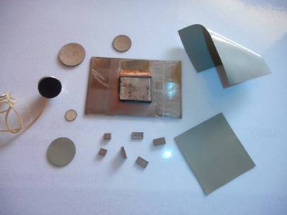
Fig. 3: PZT tape (bottom and right hand elements) and sintered ‘net-shaped’ curved discs. A curved piezoelectric ceramic disc is embedded into the mechanical sector transducer (left). A linear array with 20 elements aligned
upright is also shown (centre).
 Table 3: Piezoelectric ceramic specifications of ANSTO formulation in comparison
to commercial product
Table 3: Piezoelectric ceramic specifications of ANSTO formulation in comparison
to commercial product
 Property Vernitron 7A Toshiba C-24 ANSTO formulation
Q 600 920 <920
ε33/ε0 425 209 100-250
Kp 0.51 0.04 <0.04
K33 0.5 0.52
>0.52 d33 10-12 m V-1 150 68.2 >68.2
g33 10-3 V.m N-1 39.9 36.8 37-50
Z ( 106 kg m.s-1) 36 32 32-36
 Curie temp
(ºC) 350 255 200-350
Curie temp
(ºC) 350 255 200-350
A key challenge
of
the
composite piezoelectric project was to sinter tape ceramic to high density
strictly fails to meet the aging rate criteria of the
MIL-STD 1376B (its aging rates are too low) and
final dimensions. Linear shrinkage was
the percentage change in KT
is too high. The d33
approximately between 14-20% depending on the
solids loading but could be controlled
to +0.5%. Alumina substrates
fabricated for
production
purposes had tolerances for thickness of + 10%, and
flatness (camber) of +
0.4%, so one of the goals for
this project was to fabricate ceramic to thicknesses
of between 150-300 µm that had tolerances which were equivalent to or
better than industry standards.
Piezoelectric elements were sintered to greater than
97% of theoretical density
and
had grain sizes
between 2 and 10 µm. The bulk density and grain
size markedly
influenced
the piezoelectric properties of the sintered ceramic [22]. An outcome of this project was the development of some intellectual property centred on a process for shaping piezoelectric ceramic and fabricating arrays
from
taped material [23]. Distortion-free piezoelectric
tapes and laminates were prepared forming a variety of shapes such
as disks with curved surfaces and flat rectangular elements used to form tiers in piezoelectric/polymer composites. Figure 3 below illustrates
some of the piezoelectric elements fabricated from green tape.
The specification
of the piezoelectric
ceramic developed was based on a Hans Ruckert
formulation, and is listed in table 3 below along with a comparison
of with ceramics used by Ausonics which corresponded closely with a
modified lead titanate. The development
of this
ceramic tape technology
showed that cost was not
an impediment
to traditional machining ceramic or dice and
fill composite
arrays. However,
in the early 1990s under the direction of new management
(Pacific Dunlop Ltd) the development
of this
technology ceased.
PIEZOELECTRIC FORMULATION
AND PROCESSING CHANGES
Hans Ruckert’s 1970 patent has been the backbone
of the materials
produced over the past 40 years. Materials based on the guidelines expounded in this
patent are still in manufacture. However, the two
materials that are currently in
largest volume
production are not based on the patent.
Over the last forty years, the Thales group has had
to build transducers
and supply ceramic
components which have been “built? to print”. As
the designs invariably
come
from
the
USA or
Europe, they have specified ceramics compliant to MIL_STD_1376 (SHIPS) 1970 or its later editions such as MIL-STD-1376B (SH). On a number of
occasions, the customer has only been willing to
accept full material compliance.
As an example, we can consider the properties of the
Thales TLZ 1 material made in accordance with the
Plessey Ducon Australian patent. This material
exceeds
the
specification on
some batches. The
material also changes its capacitance under
uniaxial pressure a little more than typical lots of a more
traditional type I material.
Because of such difficulties, it has been necessary
to produce materials which are totally compliant with MIL-STD
1376B. Yet even this does not
satisfy all requirements. It is well known that PZT materials are sensitive to small amounts of dopants,
to the raw materials
used
and to the processing
steps. When all these are optimised, materials with enhanced
properties can be produced. An example of this is the TLZ 3 material which
is currently produced in the largest volumes.
With particular attention paid to the above three factors, the properties of many batches of this
material would strictly fail the MIL-STD
1376B criteria for coupling and d33. For most customers
this is a “bonus”.
A side effect of this attention to
composition and processing
has been a material
which also a significantly improved stability with
respect to voltage and pressure. The TLZ 2 formulation has been similarly enhanced over the
standard type II material.
Another ceramic formulation which is in large
volume production at
this current time is
a modified lead titanate, TL 1. The principal
dopant is calcium
titanate but there are numerous
minor additives which are designed to improve the ability to pole this material, lower its tan δ and to increase
its stability with time. This material
is similar to compositions used by other suppliers but some key
additives have been identified which are critical to achieving
the benefits
noted above. Use of such
unique compositions combined
with tight processing controls over green
and sintered densities has significant
benefits. In a recent competitive comparison,
a Thales customer praised the uniformity and consistency
of the TL 1 dielectric constant and d33 which enabled them to
reduce the system tolerances by 50%.
Further improvements to compositions
inspired by
the 1970 patent are still being undertaken in current
piezoelectric formulations. In 2012, the TLZ 5
composition and processing were modified to
produce a material
with a d33 > 900 pC/N. Potential modifications
to the high manganese doped
materials have been identified which may enable
materials with voltage stabilities similar to type III
to be produced
with d33 values similar to type I. Lastly, materials such as TLZ 4 have demonstrated
the ability to combine the stability of
a type I with
the piezoelectric properties of a type II.
Modifications are being trialled which could produce a voltage stable type V equivalent.
SUMMARY
This paper has reviewed the evolution of electronic
ceramics in Australia over the past 50 years with
specific reference to the development of dielectrics
and piezoelectric devices in targeted applications.
Although the focus of this review did not touch on
research underpinning
the
commercial
products,
there are several groups across academia and
at
national labs which continue to pursue developing materials and process technologies. These
developments will ensure that local expertise and
manufacturing capabilities remain an integral part of our niche ceramic manufacturing hub.
REFERENCES
1. Mellor, D.,
Australian War
Memorial official history ww2_civil_vol5_.
In: s.l.:
Australian War Memorial, (1958),
Chapter
21 Communications.
2. SMH, 13
July 1932. Sydney Morning
Herald.
3. SMH, 23
July 1963. Sydney Morning
Herald.
4. http://www.hrsa.asn.au/, n.d.
5. SMH, 24
June 1949. Sydney Morning
Herald.
6. SMH, 4
May 1954. Sydney Morning
Herald.
7. SMH, 14
Oct 1954. Sydney Morning Herald
8. Gleeson, J. M.,
1946. Steatite for High
Frequency Insulation. J. Br. I.R.E. Vol [6],
pp. 20-32.
9. Randall, C., 2009.
History
of the First
Ferroelectric
Oxide, BaTiO3, s.l.: American Ceramics Society.
10. Thales Austalia
Internal Report GCM04572, n.d. GCM04572 Ruckert report
History of Ceramic Capacitor Development in Australia, s.l.: s.n.
11. Thales Australia Internal report
GCM02597, n.d. GCM02597 Ruckert report
266
Survey on
Ceramic Capacitors 1971,
s.l.: s.n.
12. Thales Australia
Internal
Report GCM02599, n.d.
GCM02599 Ruckert Report
272 on NPO Dielectrics
Formulations and History, s.l.: s.n.
13. Thales Australia
Internal
Report GCM02604, n.d.
GCM02604 Ruckert Report 275
on Development of Type
2
Ceramic Dielectrics 1973, s.l.: s.n.
14. Thales Australia
Internal
Report GCM02011,
n.d. GCM02011 Hans Ruckert
Report on Design of Barrier Layer
Capacitors, s.l.: s.n.
15. Ruckert, H. F.,
Development of Piezoeelctric
Ceramics in Australia. J. Aust. Cer Soc, Vol [8], (1972), 33-37.
16. Mil-STD-1376B (SH), Piezoelectric
Ceramic Material and Measurement
Guidelines for
Sonar Transducers, US
Department of Defence 1995
17. Hiromi O et al.,
Matsushita, US
patent
3268453 (1966)].
18. Ruckert,
H.,
1970.
Australia, Patent No.
439,447.
19. Griffiths, K., 2004. An historical look at ultrasound as an
Australian innovation on the occasion of the ultrasound stamp issued
by Australia Post -18th May 2004. ASUM
Ultrasound Bulletin, August, pp. 22-26.
20. Woolfrey J. L., The feasibility study on the fabrication
of
piezoceramic/polymeric
transducer arrays, ANSTO report 1987.
21. Mistler R. E. and Twiname E. R. Tape
Casting: Theory and Practice, 2000
Published by the American Ceramic Society,
Westerville OH
22. Patel N. D and Nicholson P. S. Am. Ceram.
Soc. Bull 65 (1986) 783-79.
23. Aust patent filing “Tape Casting, Shaping and Array
Fabrication of Piezoelectric
Ceramic’ Nov 1989.