| CAPACITOR REFORMING - or
: How to avoid the Big Bang!
When a new bit of gear arrives in your workshop
- what do you do? After a quick check to see the voltage selection (if
any) is set correctly, do you apply power without further ado, just to see
what happens? |
|
Most of us - if we are honest -
have done this at some time. And most of us have "got away with it". Often
enough of the equipment powers up OK, with evident signs of life, and no
ill effects.
The problem
The trouble is that most
of us have also had the other experience! After switching on - and you are
in luck - there is only a nasty smell, maybe with some smoke - and you
switch off in a hurry. Examination shows that one or more electrolytic
capacitors is warm/hot, and possibly even bulging with evident internal
pressure. The capacitor then has to be replaced - but no great harm is
done.
If you are lucky - there is a large bang - followed by you
switching off in an even greater hurry! Examination this time, shows a
horrible, gungy mess inside the equipment, where an electrolytic has
passed away, leaving its contents scattered into every inaccessible
corner.
How to avoid a gamble
So are we faced with
this gamble every time we power up new equipment? Well, no - the
alternative is to carefully reform the capacitors before fully applying
power. Discussing this with Mike Hazell, G1EDP, revealed a piece of
equipment that he made up for this task. This handy bit of gear also tells
him whether the capacitor is OK or not - if not, he can replace it before
any damage is done.
| A memorable 'big
bang'
While at school in the
Cadet Force Signals section, I was one day repairing a WS19 power
supply. after fixing it I took it up to the physics lab for a
test.
I put the PSU (not in
its case) on the bench and applied 12 volts. Everything seemed
OK, so I left it running, and went to chat to the lab
technician.
Suddenly there was an
almighty bang, and the physics master came rushing out of a lesson
to find out what was going on. He was not pleased to find a
trail of gunge scattered across the bench and floor. A glance at the
PSU showed that the electrolytic was now no more than an empty
can. Following the trail, I was astonished to find most of the
solid contents of the WS19 smoothing capacitor sitting neatly in a
waste bin, some 3 yards from the PSU.
Richard, G7RVI
| |
Reforming the capacitors can take
some time, hours typically for those that have not seen any power for many
years - and in some cases, days. Naturally, this does require some
patience - particularly difficult for those desperate to get that new
widget up and running - but you only need one experience of the "big
bang", to teach you that patience is definitely the best
policy.
So what goes wrong with
electrolytics?
Electrolytics use a very thin film of oxide on
the positive electrode as the "insulator" between the plates. They need a
small leakage current to keep this oxide layer in place. If left unpowered
for long periods the oxide layer can break down, making the capacitor into
more or less a dead short.
When power is applied to a capacitor
in this condition, it may quickly re-oxidise, and limit the current flow.
In some cases, lots of current flows, the capacitor get hot, starts to
gas, and may also explode.
Exactly what is
'reforming'?
Reforming applies voltage to the capacitor - but
in a controlled manner so if it is a short, the current is limited to a
safe value. This allows the oxide layer to slowly reform, without
producing excessive heat and gases - although this may take several hours
to complete.
A simple capacitor reforming
unit
When I asked Mike, G1EDP about his capacitor reforming
unit, he gave me a photocopy of an article from the May 1969 issue of
Radio Constructor magazine ( now long defunct - see
Acknowledgements).
The basic principle of the unit
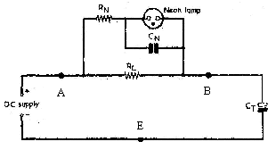
is illustrated by the outline circuit in Fig.1. CT is the capacitor being
reformed or tested. A DC supply is required, with a voltage equal to the
voltage rating of the capacitor under test. CT is connected to the DC
supply through RL, which limits the maximum current flow to a safe value,
typically a few milliamps. A visual indicator consisting of the neon lamp,
RN and CN shows the progress of the reforming and state of the
capacitor.

Fig.1: outline circuit of
capacitor reformer. |
|
1
|
|
The way this circuit works is as
follows. Initially at switch on, the voltage across BE is at zero (since
CT is presumably discharged) and the voltage AB is equal to that of the DC
supply, and the neon lights. If CT is at all healthy it will slowly (maybe
very slowly) start to reform and charge up - the voltage across BE will
start to rise, and that across AB - and the neon circuit - correspondingly
falls.
As this process continues - and
it may take hours - the voltage across AB falls to the point where it is
insufficient to keep the neon continuously alight. The neon then goes into
a flashing mode due to RN and CN. Once the neon stops flashing, the
voltage across AB is then at a low value (approximately 75 volts) and CT
is virtually fully charged, and can be assumed to have reformed
successfully. |
Design of a practical
capacitor reformer
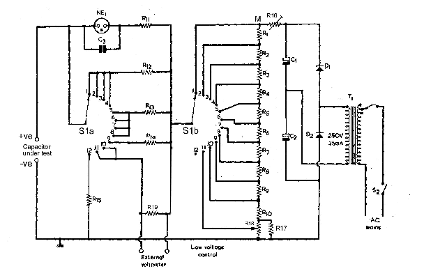
The full circuit for a capacitor
reformer is hown in Fig.2. - which has been adapted from the Radio
Constructor article already mentioned.
A simple DC supply using a
voltage doubler rectifier arrangement turns a 250V AC output of the
transformer into approximately 520 volts DC across C1 and C2. The resistor
chain R1 to R10, R16 to R18 sets the actual voltage to be used in the
reforming, and can be selected by the 12 position switch S1b. The resistor
values have been chosen to provide the voltages shown in Table 1, and have
approximately 25mA flowing through them. When setting up the unit, the
value of R16 should be chosen to that point 'M' has 500 volts with respect
to the negative rail (chassis or ground).
|
|

Fig.2: Full circuit of
capacitor reformer |
|
Acceptable leakage
current
All electrolytics leak to some degree - the question is
whether the leakage is at a reasonable level or not. What is "reasonable"
varies with the quality of the capacitor, and also its voltage rating. The
circuit in Fig.2 detects leakage currents typical of older capacitor types
- it will not necessarily work well with modern capacitors, particularly
some of the very high capacitance values now available that can have
leakage specifications up to a few milliamps. |
A capacitor with acceptable
leakage current is indicated by the neon stopping its flashing and going
out completely. This occurs when the voltage across AB, in Fig.1, falls to
about 75 volts. The values of resistors R12, R13, R14 and R19 (the
equivalent of RL in Fig.1) are chosen by:
R(kW) = 75 volts (i.e.
voltage neon goes out
at)
max acceptable leakage current (mA)
The values for these resistors
shown in the parts list (see Table 2) give the leakage currents shown in
Table 1. |
|
2
|
|
Table 1: Switch S1 settings |
|
S1
position |
Approximate
voltage
available |
Maximum
capacitor
leakage
current (m A) |
|
1 |
500 |
1,000 |
|
2 |
450 |
|
3 |
400 |
|
4 |
350 |
|
5 |
300 |
850 |
|
6 |
250 |
|
7 |
200 |
|
8 |
150 |
|
9 |
100 |
700 |
|
10 |
63 |
see text |
|
11 |
0-50 |
see text |
Low voltage
electrolytics
A slightly different arrangement is made for low
voltage electrolytics, which may be tested on positions 10 and 11, of S1.
Position 10 provides about 63 volts, and position 11 a variable voltage in
the range 0 - 50 volts. Since the neon indicator will not work at all at
these low voltages, provision is made to connect an external voltmeter
across R19 - this should be a 20kW/V meter (such as an AVO) or
better, a DVM.
R19 has a value of 10kW so each volt developed across it
indicates that 100mA is flowing in leakage current. The acceptable limit
value in this case can either be taken from the specifications, or if
these are unavailable, use a value of 0.01CV mA, where C = capacitance in
mF, and V =
applied voltage in volts.
Position 12 of
S1 is provided for safe capacitor discharge: remember a capacitor charged
with up to 500 volts can give a very unpleasant belt!
Professional capacitor
reformers
It is worth noting that there are ex-MOD capacitor
reforming units around - although I personally have never seen one for
sale, nor do I have any information on such units. You may be lucky and
pick one up at a rally - well worth getting if you see one. |
|
Table 2: Parts list for the capacitor
reformer |
|
Component
reference |
Value and type |
|
R1 – R9 |
2.2 kW , ± 5%, 2W |
|
R10 |
560W , ± 5%, ½ W |
|
R11 |
220kW , ± 5%, ¼ W |
|
R12 |
68kW , ± 5%, ¼ W |
|
R13 |
82kW , ± 5%, ¼ W |
|
R14 |
100kW , ± 5%, ¼ W |
|
R15 |
1.5kW , ± 5%, 1W |
|
R16 |
potentiometer or select on test resistor to give
500V at point ‘M’ |
|
R17 |
18kW , ± 5%, ¼ W |
|
R18 |
2.5kW linear pot, 2W
wirewound |
|
R19 |
10kW , ± 5%, ¼ W |
|
C1, C2 |
16m F, 350V
wkg |
|
C3 |
0.22m F, 100V
plastic |
|
D1, D2 |
1N4007 diodes or similar |
|
T1 |
Mains transformer with 250 – 300V, at 35mA (or more)
secondary |
|
S1 |
2 pole, 12 way |
|
S2 |
Mains on/off toggle |
|
NE1 |
Neon indicator |
Acknowledgements
The basic circuit design for
the capacitor reformer was taken from an article by T.W. Bennett,
"Reforming and Testing Electrolytic Capacitors", published in the May 1969
issue of Radio Constructor magazine.
|
| Copyright © April 2000 VMARS and Authors
Originally published in the VMARS
Newsletter,
April 2000 |
Submitted by Mike Hazell, G1EDP
Written
up by Richard Hankins, G7RVI
HTML conversion for
website by Barbara Guy, G8IEV |
|
3
|

