![]()
Mil-C-5015
PartCode Nomenclature + Visualisation
2nd Edition 9/8/25 (AWD)
Preamble:
As we know (or are forced to learn), with the complexities inherent in a standard AN9534 (Nov. 1939) as old as the 2nd WW, things either get complicated by the diversification adopted to meet new requirements, OR, new standards are created to supplant (sometimes confound) the old-school perceptions we think we can comprehend. J The original US defence standard was MIL-C-5015 (Jul. 1949) and technology etc. and engineering make new demands to meet our evolutionary needs.
After MIL-C-5015 Issue “H” (or later?) a newer standard MIL-DLT-5015 is now-a-days becoming
dominant.
Environmental classifications, removable crimp contacts (as an option to the traditional solder-pot
termination) and some updated electrical ratings are amongst the
improvements within later versions of the original standard.
Applications:
Typical modern-day applications include.
Heavy
& Off-Road Vehicles, Industrial, Military Ground Vehicles,
Oil and Gas, Factory Automation and
Robotics etc.
Brief Guide
to MIL-C-5015 Screw-Coupling
Multipole Connectors
Caveat-Emptor:
Standards do address the critical basics to ensure intermateability and other essential quality conformance and compatibility, however, given the diversity provided within the general specification, and the interpretations applied by individual manufacturers (especially in some accessories etc.), reference to manufacturer’s data needs to made to verify that all relevant details meet the needs of the intended application.
Quality Expectations:
QPL certification is the premium quality guard afforded by the military and avionics industries but such cost is rarely justifiable in the industrial and general-use market place in which these find current applications.
In their basic form Mil-C-5015 (solder contact terminated) connectors serve industries needs for robust electrical interconnections and their relative affordability has evolved from volume production and the confidence of users/specifiers in their performance, as directed by the original standards, and their ongoing availability for new production and maintenance.
Selection Criteria:
Initial selection criteria that need to be established to help direct users to the connector options include:
1) Current carrying capacity (or wire-gauge) for each conductor to be connected
2) Number of contacts to be provisioned for each wire’s current capacity
3) Mounting style
4) Polarity assigned to each connector body/style
5) Environmental criteria
Enquiring & Ordering:
In making enquiries, please help us by suppling the following details wherever possible:
1) Full part numbers (military or manufacturer’s) including any known options that may be considered.
a. Where required for maintenance purposes, supply of images and measurements is often very helpful.
2) Quantity required
3) Delivery time-line
4) Shipping destination (if not to your registered address)
5) Any specific details desired to qualify the product including data-sheets, drawings etc.
Analysing 3 Typical Examples: (picture images are style-representative only)
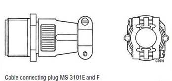
MS3101F28-22S-BRAND
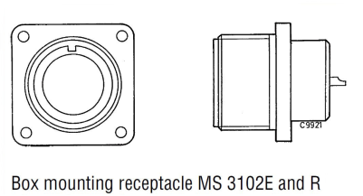
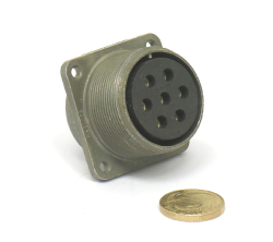
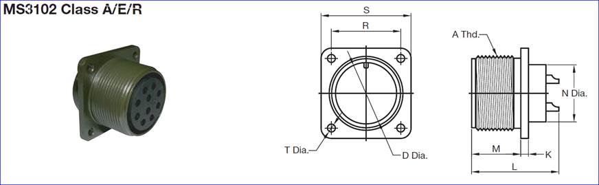
MS3102R28-22S-BRAND
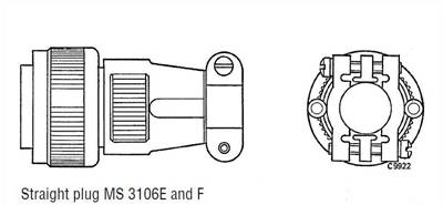
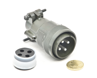
MS3106F28-22P-BRAND
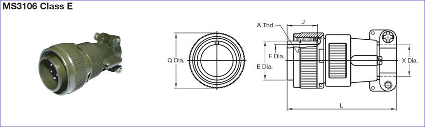
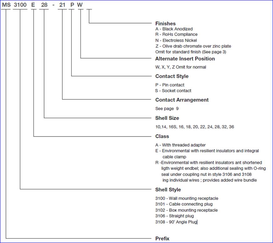
Decoding the Above:
MS = basically according to Mil-C-5015 or MIL-DLT-5015 (or permitted variants upon according to manufacturer’s choice where permitted).
310X = the various connector body style/format (according to the standard and/or specials made by individual manufacturers).
A~R = letters to help define the contact-attachment/termination and the environmental classification afforded by dielectric, body, back-shell and associated accessories (that the mated connector can meet)
28 = shell-size in units of
1/16” in the engagement thread size according to the size table from size 8 (1/2”UNEF
28tpi) to size 48 (3”UN 16tpi)
22 = contact arrangement/pattern of 3 x #4 + 3 x #12 contacts according to standard with the contacts pre-installed in the insulation (these numbers, within the 5015 family, very rarely equate with the number of contacts)
P/S = the contact form (P= pin, S = socket)
BRAND = other suffixes may be added to define special features including polarisation and finish.
CASA’s brand or other OEM brand-suffix as adopted by CASA Modular Systems.
These typical letter codes “A” ~ “R” etc. define the ‘Classification’ relating to the environment and the appropriate styles of backshells and cable clamps that are appropriate to the ‘service’ conditions that the assembled connectors can meet (but not exceed). Of course, in the evolution and deviations of the original, some makers have their own interpretations/variations and, there are newer environmental classifications included in the updated standard now called MIL-DLT-5015
To describe the current F & R classifications in the above examples:
“F” =
an improved version of the older “E” class (now becoming obsolescent) and this
includes the integrated back-shell with cable clamp that you seem to prefer.
“R” = basically applies to the female (with pin or socket contacts) where an o-ring is provided (installed) to achieve the environmental classification.
In the choice adopted for expediting orders, connectors that exceed customer’s environmental requirements may be offered where they are not available in current ex-stock delivery. Other options, including refurbished connectors, may be negotiated to expedite urgent-maintenance needs without suffering factory minimums and production-cycles or international shipping etc.
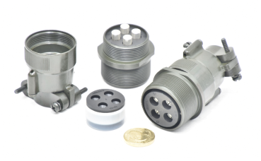
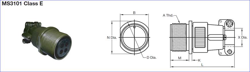
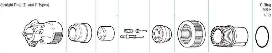
Typical Mil-C-5015 Connector Parts:
Below is an expanded illustration of a typical MS3106F to help establish design and assembly visualisation:
Classification Letters:
“A” =
an early version, sometimes with phenolic-moulding contact block and removable
contacts (Amphenol industrial-grade without particular environmental rating) of the older “E” class (now
becoming obsolescent) and this typically includes the ORIGINAL back-shell
and early (primitive) cable-clamp.
“B” = a split back-shell (enables checking the engaged/mated connector without major disassembly)…
“C” = a pressurised rating for bulkhead sealing…
“E” = environmental grade …
“F” =
an improved version of the older “E” class (now becoming obsolescent) and this
includes the integrated back-shell with cable clamp that you seem to prefer.
This can achieve an IP67 rating (or
higher).
“K” = a fire-wall rated connector…
“M” = replaced by “E”…
“R” = basically this applies to the female (with pin or socket contacts) where an o-ring is provided (installed) to achieve the environmental classification.
Summary of Nomenclature: (according to our prime supplier but there are other designations & descriptions in the market)
Briefly Moving
Along – Crimp Removable Contacts etc.
Crimp-Contact MIL-C-5015E:
This generation provides removable (front release) crimpable contacts while retaining much of the range of configurations available with solder-contacts but drops most of the earlier service classes except “R” and adding “K” and “D”.
MS = basically according to Mil-C-5015 or MIL-DLT-5015 (or permitted variants upon according to manufacturer’s choice).
340X = the various connector body style/format (according to the standard and/or specials made by individual manufacturers).
Crimp-Contact MIL-C-5015F:
Rear release crimp-contacts and higher temperature rating etc.
CASA Sales Department
Phone: +64-4-9393777
Email: sales@casa.co.nz
![]()
http://www.casa.co.nz
http://www.casamodularsystems.com
Site-Map:
http://casamodularsystems.com/index.php?main_page=site_map