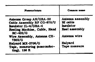
6. Common Names7.
Description(fig. 2)a. Bag BG-175,
made of heavy canvas,is used to store all
components.b.
Each Reeling Machine, Cable,
HandRC-432/G
consists of a reel on which 160feet
of Wire Assembly, Antenna CX-7303/G is wound. A terminal hook on
theloose end of Wire Assembly,
Antenna CX-7303/G attaches to
Insulator IL-4/GRA-4.Halyard
MX-2706/G is secured to a smallhole
in the Reeling Machine, Cable, HandRC-432/G frame. A spring action
handleon the outer flange of
the spool facilitateswinding.c. Cable Assembly, RF CG-678/U is
75feet 3
inches long and consists of
cableRG-58A/U with a connector
UG-536/U ateach end.
Cable Assembly RD CG-78/Uconnects between Insulator
IL-4/GRA-4and the radio
set.d. Insulator IL-4/GRA is a
phenolichousing which has two terminals for con-nection of the antenna wires and a
femalecoaxial fitting
for connecting Cable As-sembly RF CG-678/U.
Insulator IL-4/GRA-4 is installed at the
center of theantenna assembly.e. Halyard
MX-2706/G consists of
75feet
of l/8-inch diameter
Dacron rope.A snaphook fastener at one end of the ropeconnects to Reeling Machine, Cable,
HandRC-432/G, a snaphook fastener
and a leadweight is attached to the
other end.f. The tape, measuring (tape
measure),made
of nonconducting woven fabric,
is156 feet long. It is
calibrated on one sidein feet and on
the other side in frequency.It is
used to measure the length of antennanecessary for operation at any
given fre-quency.
The tape measure is marked
ateach 100 kilocycles (kc)
from 1.6 to 6 mc,at each
200 kc from 4 to 6 mc, at
each500 kc from
6 to 10 mc, and at each
mcfrom 10 to 20
mc.7