|
This tutorial will show you how to use the
IntelliCad 2000 & new versions 4SE &
5SE & 6SE programs
to draw your
part.
Then to draw
an outline of the cutter tool path.
No need to know
the Gcodes with CAD.
-
To start select Insert
-
Then select Circle Function
-
Draw the Circle to the
Diameter you wish to Machine.
-
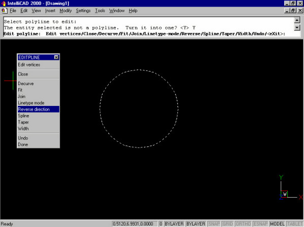
Then from the Modify Menu
-
Select Edit polyline to change the Circle to a Polyline.
Then select Yes> Turn into a polyline
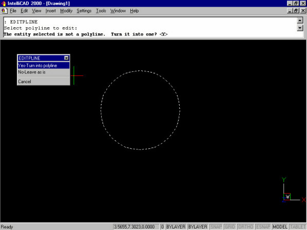
To change the direction the cutter will move.
CAD programs draw in a CCW direction.
The Gcode for this is (CCW) G03 or (CW) G02
So we will select Reverse direction
from the menu.
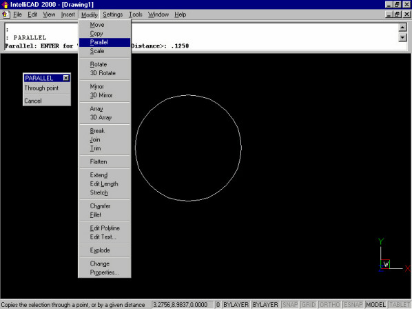
Now that we have converted to a Polyline. The cutter Diameter has to
be known next.
Let's choose a 1/4"(.250) end mill to machine the part.
To draw the tool path for the Cutter Diameter offset of 0.125 half
the cutter Diameter.
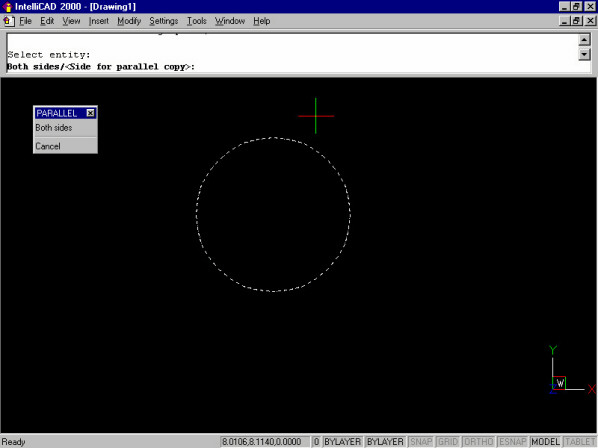
Select the Modify Menu
Then select Parallel
Then type the Distance>: .125 to
offset
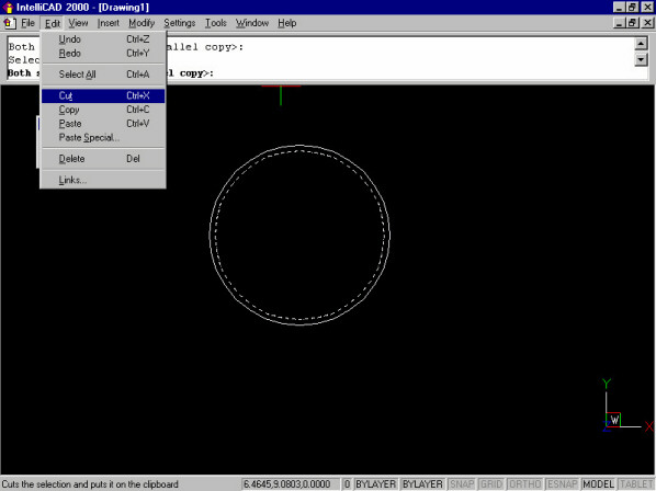
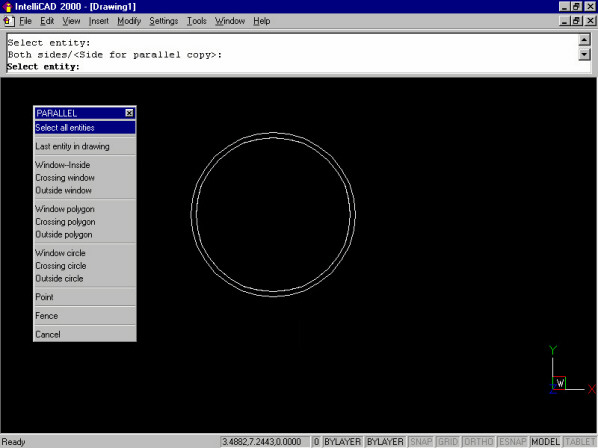
This screen is where to decide if you want to offset to the outside or insde of the Circle?
Mouse click to the outside of the Circle.
The outside Circle is the cutting
tool's path with a .125 offset.
Using Cut to make the Outside offset the
Tool Path.
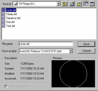
Save the Outside Drawing as Circle.dxf or give the file a new
name.
Circle.dxf is ready for Gcode conversion.
You can Buy a DXF to Gcode Conversion Program click
here
Click here to download more Help Using the Intellicad
Commands for CNC.pdf |