|
Stepper Motor Driver DQ542MA | |||||||||||||||||||||||||||||||||||||||||||||||||||||||||||||||||||||||||||||||||||||||||||||||||||||||||||||||||||||||||||||||||||||||||||||||||||||||||||||||||||||||||||||||||||||||||||||||||||||||||
|
Product No.: N201142191639 | |||||||||||||||||||||||||||||||||||||||||||||||||||||||||||||||||||||||||||||||||||||||||||||||||||||||||||||||||||||||||||||||||||||||||||||||||||||||||||||||||||||||||||||||||||||||||||||||||||||||||
|
| |||||||||||||||||||||||||||||||||||||||||||||||||||||||||||||||||||||||||||||||||||||||||||||||||||||||||||||||||||||||||||||||||||||||||||||||||||||||||||||||||||||||||||||||||||||||||||||||||||||||||
Introduction: DQ542MA is a two-phase hybrid stepping
motor driver. The drive voltage is from 18Vdc to 50Vdc. It is
designed for use with 2-phase hybrid stepper motor of all kinds
including 42mm to 86mm outside diameter and less than 4.0A phase
current. This circuit that it adopts is similar to the circuit
of servo control which enables the motor run smoothly almost
without noise and vibration. holding torque when DM542A run
under high speed is also significantly higher than the other
two-phase driver, what is more, the positioning accuracy is also
higher. It is widely used in middle and big size numerical control
devices such as curving machine, CNC machine, and computer embroider
machine, packing machines etc.
Features:
Electrical specification:
Pins assignments and
description:
1) Connector
Pins Configurations
2) Pin wiring diagram:
PCs control signals can be active in
high or low electrical level. When the high electrical level is
active, all control negative signals will be connected together to GND. When low electrical level is active, all control positive
signals will be connected together to public port. Now give two
examples (open collector & PNP), please check
them:
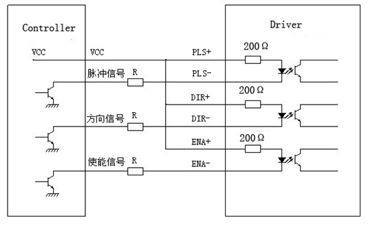
Fig 1. Input port circuit (Yang
connection)
PC open collector output
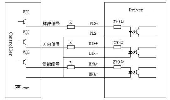
Fig. 2 Input port circuit ( Yin
connection)
PC
PNP output
Note: When VCC=5V, R=0
When
VCC=12V, R=1K, @ 1/8W
When
VCC=24V, R=2K, @ 1/8W
R must connect in the control signal
port .
3.Function choice (using DIP pins
to achieve this function)
1) Micro step resolution is
set by SW 5,6,7,8 of the DIP switch as shown in the following
table:
2) Standstill current
setting
SW4 is used for this purpose. OFF
meaning that the standstill current is set to be half of the
selected dynamic current and ON meaning that standstill is set to be
the same as the selected dynamic current.
3) Output current setting:
The first three bits (SW 1, 2, 3)of the
DIP switch are used to set the dynamic current. Select a
setting
Closest to your motor's required
current
4) Semi-flow
function:
Semi-flow function is that there is not
step pulse after 500 ms, the driver output current automatically
reduced to 70% of rated output current, which is used to prevent
motor heat.
4. Pins of motor &
power:
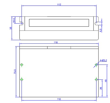
5. Mechanical
Specification:
To have 20mm of space around, cannot be
placed next to other heating devices. Whats more, avoid dust,
oil mist, corrosive gas, heavy humidity and high
vibration.
6. Adjustment of
troubleshooting
1) , the status on lights
indication
PWR: green, normal work light. ALM: red, failure light, the motor with phase short-circuit, over-voltage and under-voltage protection. 2) Troubles
7. Driver wiring
A complete stepper motor control system should contain stepper drives, DC power supply and controller (pulse source). The following is a typical system wiring diagram 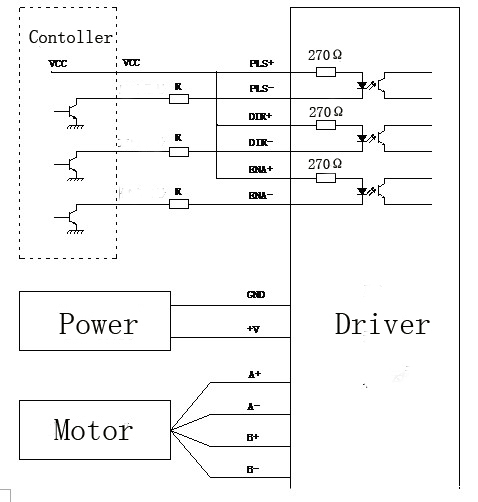 8.
APPENDIX
Twelve Month Limited
Warranty
WANTAI MOTOR. warrants its
products against defects in materials and workmanship for a
period of 12 months from shipment out of factory .During the
warranty period, WANTAI MOTOR will either, at is option, repair
or replace products which proved to be defective.
Exclusions
The above warranty does not
extend to any product damaged by reasons of improper or inadequate
handlings by customer, improper or inadequate customer wirings,
unauthorized modification or misuse .or operation beyond the
electrical specifications of the product and/or operation beyond
environmental specifications for the product.
Obtaining Warranty
Service
To obtain warranty service, a returned
material authorization number (RMA) must be obtained from customer
service at e-mail: sales@wantmotor.com.
Before returning product for service.
Customer shall prepay shipping charges for products returned
to WANTAI MOTOR for warranty service, and WANTAI MOTOR
shall pay for return of products to customer.
Warranty
Limitations
WANTAI MOTOR makes no other
warranty, either expressed or implied, with respect to the
product. WANTAI MOTOR specifically disclaims the implied
warranties of merchantability and fitness for a particular purpose.
Some jurisdictions do not allow limitations on how long and implied
warranty lasts .so the above limitation or exclusion may
to apply to you, however, any implied warranty of
merchantability or fitness is limited to the12-month duration of
this written warranty.
| |||||||||||||||||||||||||||||||||||||||||||||||||||||||||||||||||||||||||||||||||||||||||||||||||||||||||||||||||||||||||||||||||||||||||||||||||||||||||||||||||||||||||||||||||||||||||||||||||||||||||