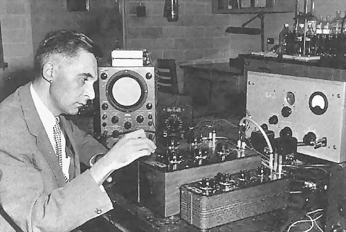
Figure 1: P. Delahay carrying out a double-layer experiments using an a.c. bridge (Louisiana State University, Baton Rouge, early sixties)
Bridges are among the most accurate types of measuring devices used in the measurement of impedance. In addition, bridges are also used to measure DC resistance, capacitance, and inductance. Certain types of bridges are more suitable for measuring a specific characteristic, such as capacitance or inductance. Theory of electrical bridges is briefly written here.
Figure 1 shows an example of a bridge setup used in an
electrochemical laboratory.
|
|
Figure 1: P. Delahay carrying out a double-layer experiments using an a.c. bridge (Louisiana State University, Baton Rouge, early sixties) |
Figures 2-24 show examples of bridges used in the beginning -
mid 20th century.
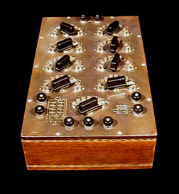 |
Figure 2: Resistance Decade Bridge
This decade bridge is a form of Wheatstone bridge, a device to measure electrical resistance. This bridge provides two of the four arms of the complete Wheatstone circuit, and the unknown and a standard resistor had to be added. A battery and galvanometer were also attached externally. |
 |
Figure 3: Post Office Bridge with
Meter
This is a Wheatstone bridge designed to locate a short circuit in a telephone or telegraph line by measuring the resistance of the wire to the short. It is called a "post office bridge" because this design was adopted by the British Post Office, which operated telegraph and telephone services as well as delivered mail. This bridge, which is in a box, has a built-in galvanometer. The upper plugs determine a ratio and the lower rows are a standard resistance. |
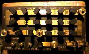 |
Figure 4: Resistance Bridge
Made in Cambridge UK, 1916 Polished wood case with bakelite panel, brass plugs for resistance selection and brass terminals. Designed for line testing, two10 ohm arms and one variable 100 ohm arm. |
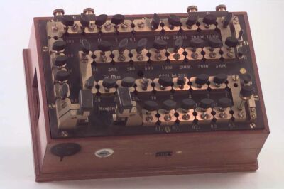 |
Figure 5: Resistance box (Wheatstone
bridge) Made by Otto Wolff, Berlin The top is in thick ebonite and the brass blocks are lozenge-shaped and undercut. Provided with resistance coils of thick wire for preventing heating when using strong currents. Twin semi-cylindrical contact surfaces are connected by insertion of a plug; this shorts the resistance coil on the bobbin. The 37 plugs are interchangeable and have ebonite handles. |
This resistance box is a two-terminal variable resistance so
designed that any desired known non-inductive resistance may be introduced into
the circuit of which it is a part. In the dial-type box several dials are
arranged in decades, so that internal switches select the desired resistance.
For example, one dial may select any number of thousands of ohms from one to
nine. The next, any number of hundreds of ohms from one to nine; the next, any
number of tens of ohms, and the fourth, any number of ohms from one to nine.
Thus by manipulating all four dials, any value from 1 to 9999 ohms may be set to
the nearest ohm. In the plug-type box, such as this made by Otto Wolff,
resistance is inserted by removing a plug, which, when in place, short-circuits
the resistance. The plugs must, therefore, be kept clean, and when removed from
the box, placed on a clean sheet of paper. They are inserted with a clockwise
motion, with only slight pressure. When a slight resistance to turning is felt,
a good contact has been obtained. In fact this device is configured as a
Wheatstone bridge, with terminals and key switches for a battery and
galvanometer. An unknown resistance can be clamped between the heavy clamp
connectors provided with silver contacts and the bridge balanced with an equal
resistance of unshorted coils between 0.1 and 50 000 W. The coils are of
manganin resistance wire, the resistivity of which does not change appreciably
with small changes of temperature. The accuracy of such a resistance standard
may be taken as ± 0.25%.
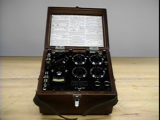 |
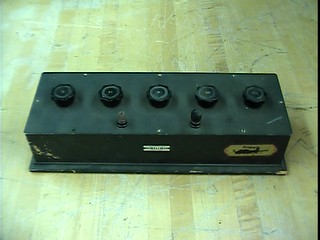
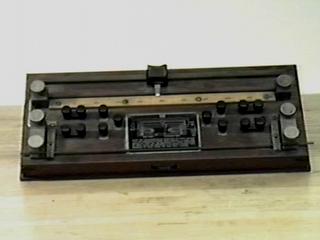
Figure 6: Wheatstone Bridge
Made by Leeds & Northrup Co., Philadelphia, U.S. |
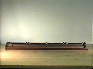 |
Figure 7: Slide Wire Wheatstone
Bridge Made by Leeds & Northrup Co., Philadelphia, U.S. This slide wire bridge is used to study the variation of
resistance of a conductor with length, diameter and material. |
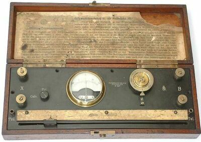 |
Figure 8: Bridge
(unknown model) Made by Hartmann & Braun |
 |
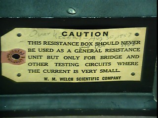 |
Figure 9: Welch Bridge Resistor
Made by W.M. Welch Scientific Company |
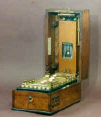 |
Figure 10: Bridge with a mirror
galvanometer Made by Chauvin et Arnoux, France |
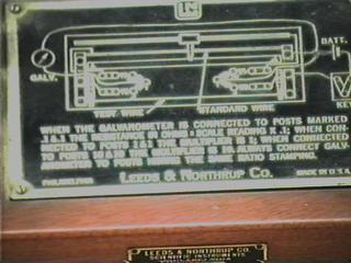 |
Figure 11: Kelvin Bridge Made by W. M. Welch Scientific Company The Kelvin bridge was designed to measure low resistances in the range of .00001 to .01 ohms. The device consists of a calibrated manganin rod with a maximum resistance of .01 ohms. One potential terminal is fixed, the other is a sliding contact. The 15 inch scale is divided into 100 equal divisions of .0001 ohm. Unknown samples 3/8" in diameter and 18" long can be measured. The connection diagram is shown below the instrument. |
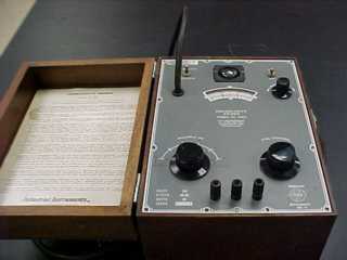 |
Figure 12: Conductivity Bridge, Model RC1682 Made by Beckman Instrument, U.S.A. See additional pictures of this device. |
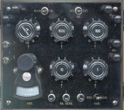 |
Figure 13: Resistance Bridge, Type
ZM-4B/U
Typically used for telephone line measurements, including open and short location |
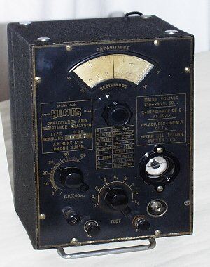 |
Figure 14: Resistance Capacity Bridge, Type CRM Made by HUNTS, 1940's. |
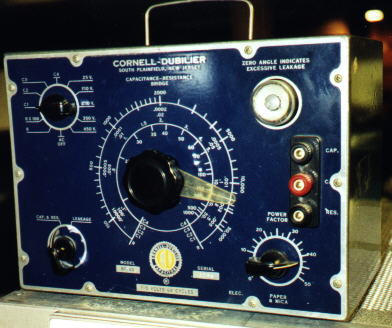 |
Figure 15: Capacitance-Resistance Bridge, Type BF-60 Made by Cornell-Dubilier w/"tuning eye" tube |
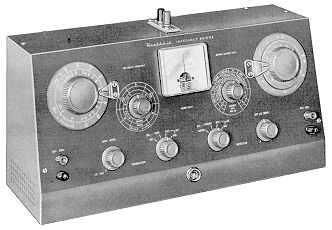 |
Figure 16: Impedance Bridge, Model
IB-2A Made by Heathkit, 1958. The IB-2A is a self-contained, direct reading precision laboratory instrument designed for rapid and accurate measurement of resistors, capacitance, inductance, dissipation factors of condensers, and storage factors of inductors. It employs a Wheatstone Bridge, a Capacity Comparison Bridge, a Maxwell Bridge, and a Hay Bridge in one compact package. Measures resistance from 0-.1 ohm to 10 megohms, capacitance from 100 mF to 100 mF, inductance from 0-.1 millihenry to 100 henries, dissipation factor (D) from 0.002 to 1, and sorage factor (Q) from 0.1 to 1,000. A 100-0-100 mA meter provides for null indications. The usual headset or other devices for such measurements are not necessary although provision is made for using an extermal detector when desirable. The decade resistors employed are of ½% tolerance for high accuracy. The IB-2A has its own built-in power supply, 1,000 cycle phase shift generator, and a vacuum-tube detector. A special 2-section CRL dial insures convenient operation. Provision is also made for connecting an external generator for measurements at audio frequencies other than 1 kH. Battery-type tubes are used so that a warm-up period is not required and measurements can be made quickly. They also eliminate changes in operating characteristics due to thermal effects. |
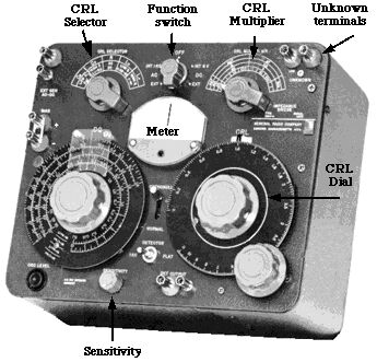 |
Figure 17: Impedance bridge |
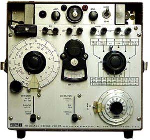 |
Figure 18: Impedance Bridge, Model 250
DA Made by Electro Scientific Inc. This is an LCR bridge with external generator or 1 kHz internal source. It measures inductance, capacitance and resistance. Resistance range: 0.1 milliOhms - 11 MOhms; capacitance range: 0.1 pF - 1100 mF; inductance range: 0.1 microH - 1100 milliH. |
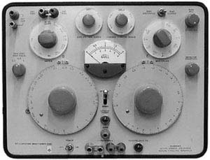 |
Figure 19: Capacitance Bridge, Model
1617A Made by General Radio Co., Cambridge, Mass., U.S.A. |
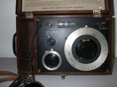 |
Figure 20: Inductance Bridge
Made by General Radio Co., Cambridge, Mass., U.S.A. (from collection of Kevin K. O'Neill) |
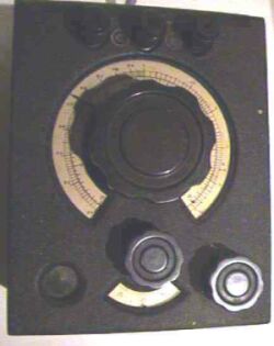 |
Figure 21: Bridge Type GM4140 CR
Made by Mullard Housed in black crackle finish steel box with magic eye null detector. |
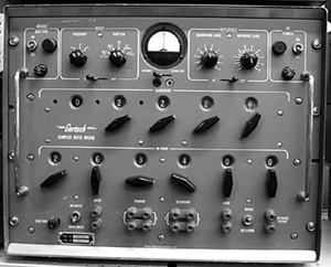 |
Figure 22: Complex Ratio Bridge, Model
CRB-4R Made by Gertsch CRB-4R |
 |
Figure 23: Universal Bridge
Made by Siemens GmbH, Germany Mainly used for maintenance of telegraph and telephone cables. |
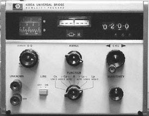 |
Figure 24: Universal Bridge HP 4260A -
LCR Made by HP HP's 4260A is easy to use, quick to set up and makes for fast measurements. It uses mechanical digital readout for RLC and has handy direction indicators. Resistance range: 10 mOhms to 10 MOhms. Capacitance range: 1 pF to 1000 mF. Inductance range: 1 mH to 1000 H. Internal oscillator is 1 kHz sine and an external oscillator input is on the rear panel. |
![]()