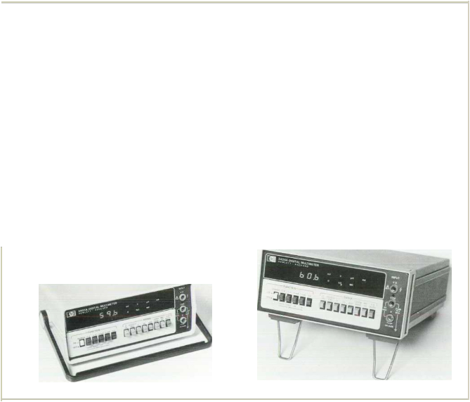
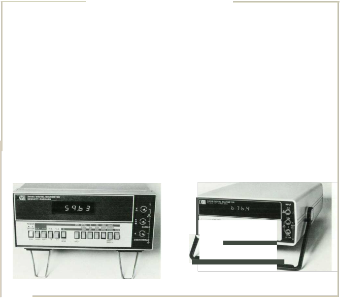
'. ooe 35A D g :a · u11meter IS a 3 2 a g: ns:rume 1U"at
1'1as oeue• accuracy (0 1°o) man Mooe 76,!, a N ae·fre
Q:;ency range for ac s gna.s (to 100 f.HZ) and t11gher sensl! vsty
1or res stance rreasuremef'ts (10-rnll resolut1on) 1: measures de and ac volts wttr full-scale rarges from 200rrV :o 1200V res sra ce troiT' 200 lull-scale to 20 Mfl, a!ld de ana ac cc.•rent rang ng f•orr. 200 JLA fu -sea e to 2000 m!. w th automat c po anty nd ca;1on ana e tner ma!'lua or a..rof"la:c range se ec· ton (excep:Nner. measur rg cu•ren:) Llgne· a ront-oane an nunc ators snoN me ;unction ana range se ecreo
An optiona • toucrH"lO d prooe enao es avo rage read1ng to be reta•neo Of' 01splawllen a pushoutton sw tch on &ne orobe bOO)' 1s pressed. Th1s lacrll!ates measurements n s.ruavons where 11 may be d1ff1cult to hold the probe 1n pos1t1on wn11e loo1<1ng away to read the measurement
Press1ng the button on the probe grounds the amperes 1nput.
wh1ch 1s convened to a log1c Input whenever the instrument IS switched to e1ther the de or ac volts mode. Ground1ng the amperes 1nput1nterrupts the voltmeter's log1c c1rcu1ts so voltage sampling IS stoppeo and the most recent read1ng 1s reta1ned on
an atlenuator, usi ng a switched feedback network for the various ranges as shown in F'ig. 4a. The opera tional amplifier establishes a virtual ground at the summing point at its inverting input where the switches are. The problem with MOS transistor back-gate bias is thus eliminated. The problem with the ON resistance remains, however. The ON resis tance in series with the 1-kO resistor of Fig. 4a must satisfy the following relationship if it is to introduce less than a one-count error in a fu11-scale reading in a
2000-cou n t (31/2-digit) voltmeter:
R .;:; 1000!1_ 0.50
ON 2000
This is a value much lower than that realizable at the present lime.
The effect of the MOS transistor ON resistance can be reduced significantly by shifting the summing
c spay t:.e.eas ";j e ouuon resto•es norfTla ope·«tor
Mooe 3435,:.. s powe·eo oy a sea ed eao-ac d storage ba'·
tery tnat cag 'e more than 10 "'ou•s o!cor.n· uous operat on
\', :non y 12 '-ou•s rech&•ge (abu It- n cnargens rcluded) W th a nev. n gh-er c ePcy LEDd spay thevo tme:er o ss1pa•esonly three watts not only extend rg batte·y ll'e Ol..ot a so enhanc ng
accuracy. stab ard re ab ty by keep '1Q ":.err a tempera tures ow
Mode 3 35!. uses te f ne·ne res srors anc the s ng e re•erence A-•o-D converted· escr bed n ·r.eaccompan} ng ar tie e giV ng rt h•gn-grade performance a1 ow cos; Serv c ng
ana ca 10•a:.on costs a•e also ow because :here are on! our potent ometers ana rwo capac,:ors tha;requ readJUStment dur Ing rout1ne ca. brat1on procedures
The nstrument1s housed 1n a tough plast1c case. well sUited for appllcallons reqUJnng portab1l1ty The carry1ng handle dou
bles as a bail, be1ng able to rotate through 15 pos111ons, each
secured by a pos1t1ve IOCk1ng detent An opuonal vers1on (Opt
002) 1s 1n a modular cab1net that can be rackeo or stacked wnh orher HP modu1ar 1ns•ruments (see pt1oto be ow)
point to the other side of the MOS switches and then using additional MOS switches to connect the ap propriate summing point to the amplifier's inverting input, as shown in fig. 4b. The 0!\: resistance of a MOS switch in series with the 10-MO input resistance easily satisfies the relationship (for a 1-count error in a 2000-counl voltmeter):
R .;:; 10X 106!1 = 50000
ON 2000
The switches between the summing points and the amplifier's inverting input contribute negligible er rors because very little current flows through them.
To prevent errors from source-to-substrate leakage currents in the OFF switches, the MOS switch fabrica tion process must be carefully controlled. A 200-mV input to the attenuator of Fig. 4 results in a mere 20 nA flowing through the 10-MO resistor. This corres· ponds to 10 pA per count in a 2000-count volt-
23
© Copr. 194B-1998 Hewlett-Packard Co.
0.1-lOOOV Input
•

.. ........
lkH
10k0 tookn tMn
10MO
![]()
![]()
meter. Thus, the sum of all leakage currents must be less than 10 pA to avoid errors from this source.
Lower-Cost Circuits
New ideas in circuit design continue to reduce the number and precision of parts used in multimeters. An example is the dual-slope A-to-D converter widely used in digital multimeters. A simplified diagram of one such converter is shown in Fig. 5. If Rl and S2 were removed from this diagram, the result would be
an autozeroed single-polarity (V10 0) converter of
Hi
tOMO Lo
(a)
51
![]()
tkn
O.IV
Output
traditional design.
The conversion cycle starts in autozero with Sl to ground and the voltage building up on C2 causing the current flow through Cl to go to zero. The resulting voltage on Cl is the difference between the integrator
and comparator offset.
Hi
Lo
(b)
tOM O
55
10MO
56 510
![]()
• •
Next, S4 opens with C2 holding the zeroing voltage and Sl connects to the input voltage. Integrator capacitor Cl now charges for a fixed time established by the control circuit. Then, Sl switches to ground, S3 closes, and C1 discharges until it reaches the au tozero voltage. At this time, the comparator changes states signaling the end of discharge. The time to discharge is proportional to the input voltage.
![]()
Dual-polarity operation has been added to this basic circuit by switching R2 to a -lOV reference or by using an op amp circuit that inverts the +lOV
Fig. 4. (a) Range-switching arrangement. (b) Modiftcalion that reduces effect of M05-tranststor ··on·· resistance. Here,
51 and 56 are swttched on to select one range, S2 and 57 (not shown) select another, and so on to 55 and 510.
![]()
reference to create a negative reference, or by charg ing a capacitor with the +10V reference and switch ing both ends of the capacitor to create a negative reference. The same result can be accomplished by
![]()
51
Input
![]()
![]()

..... C1
![]()
Comparator and Slope Amplif ier
Voltage
Input
Amplif ier 53 52
R 2( = Rl) A t
+10V .. Reference
Integrator '"7
Amplifier If
Autozero _l_
Amplifier '\1
To Logic
Circuits
S4
C2
Switch No.
On
54 OH
On
51 OH
52 On
OH
53 On
OH
Autozero Run-up
Indicates Logic for V;n<O
Indica tes Logic Modification for V;n>O
Run-down
swttchmg to a negative reference.
24
![]()
© Copr. 1949-1998 Hewlett-Packard Co.
![]()
Extending the Ranges of a Di gital l\tlultimeter
Presen•-oao g ta mu • meters typiCa
ranges 'o• eacn funct bu by ta' ng aov an;age o' t : g!l
pvt rr.peda ces and ow put bas cu•re..,•s cha•ac•e• ...t c o1 tOday s mu 'lfT'eters th vo •meter moee. res star.ces and curren·s beyond those spec r.ed tor the mu 1rr:e·e· ca" be
rr>asurea
Very High Resistances
Res•stancewe I liO •":e g•gaohm reg•or are eas ly made w•th the a•d 01 an externar source and the se1-up snown .n the d•agram The mult•meter •s 1n the de volts mode
Rx
RoMM (10Mfl)
DMM
The unknown •S found by eva uat.ng the formula
R R ( vJ > cE-vo"v )
• - l ,.... v
DIIV,
For example, 1f VsouRCE •s 10V de R0,1v •s 10 Mn and Vo•m •s
100 mV
R, = 10Mn( .!Q QJ_ ) = 990 Mn
01
If the DMM •nput resistance 1s very h1gh, say > 1o•o. 11 1s a s1mple matter to arnve at reasonable numbers by paralleling the
1npu1 w•th a 10 Mn res1stor
Very Low Currents
A d1g1tal mult1meter can be used 1n lhe de volls mode as a nanoammeter where the mulllmeter s 1nput res1stance serves as lhe current shunt, as shown 1n lhe d1agram below
lx
1.111MH RoMM (10Mfl)
OMM
using only Rl a nd $2, as shown in Fig. 5. S2 is left on during autozero so the effect of its current is nulled, just lik e other currents flowing in to the integrator. S2 is left closed continuousl y until a negative current is required at th e integrator. Then by opening SZ, t he removal of the precis ion positi ve current through Rl appears to th e integrator like the application of a precisi on negative current.
Acknowledgments
Con tri b u tors to th e desig n of the Mod el 34 76A Digi-
-he ..mknown cur•en· s der ved b eva a:"':;; tne·o m a
"'v.
Ro· '-1
If VoM'..4 we•e 100 rnV and RcMM .vere 1C • .n ,1o. u d oe 10.A
It :he nput 1•.ere para e ed t1-J a 1 111 Mn res stor.the e"ecilve
Rilw1 wouldDe 1 Mn ana me rnult me!e• would;r:en read mnano
amperes o•rectt y
Pitfalls
Obv•ously, a manufacturer could Include 1hese ranges •n the ong1nal des•gn Why doesn'l he? The pnmary hm1t1ng factor s Input b•as current No matter how good the 1nput ampl1f1er may be, !here IS a small amount of b1as current typ•cally 10 to
100 pA, that can Interfere w1th the measurement. and thiS cur
rent can change drastically w1th temperature A vottage read
•ng taken wnh the unknown Impedance connected wh1le no s•gnalIS applied will 1nd•cate lhe amount of error attrbutable to tne •nput b•as current
A second hm111ng factor •s the voltage appl.ed 1n the ohms mode To prevent component damage 1n •he c•rcLut under test,
the open-c•rcun voilage of most DMMs 1n tne ohms mooe 1s
hm•ted to 5 volts de No suchconstra•nt ex•sts w'ten an externa
source •s used but the operator snou•devaluate the poss1b1 •t es lor damage beforehand Also,11 very h1gh voltages are used tor very h•gh res•stances. prudent sh•eld1ng should be the rule and a h1gn-qua 11y capac•tor ought ro be connected across :he mult.meter mput 10 reduce no1se
Trading Resolution for Reduced Burden
There are t•mes when mak1ng measuremems of current or res1stance at less than 10% of full scale may result •n more mean1ngful results. In measurements of current. for example, a typ•cal voltage burden (voltage drop across the DMM •nput lerm•nals) of 100 mV would be reduced to 10 mV by sw1tch1ng to the next h1gher range Measuremenl accuracy and resolut•on are reduced by a factor of 10. but may st1ll be h1gh enough for many measurements The disturbance to the measurement
caused by the voltage burden. on the other hand, IS also re
duced so ml?'lSLifemE>nt accuracy may actuallbe •ncreased
For res1s1ance measurements. a typ1cat 1-volt burden IS re
duced to 0 1 voiJ oy go•ng to the next higher range In many
•nstances thiS would reduce errors caused by conduc•,on •n sol•d-state dev•ces. aga•n enhanc•ng accuracy
tal Multimeter were Roy Buck, Tom Mills, Mike Al lender , a nd Don Aupperl e (industrial design); t o the Mod el 34 35A, Bill Hale, Gary Stadele, Bob Jarvis. Marsh Fa ber, Bob Moomaw , Bob Livengood, Ed Pen nington , John Shea , Dave Connell , and Jim Berry (in du stri a l desig n ); to the Model 3465A, Craig Walters (Group leader). Ed Pennington , Francis Fiedler, Jim Fulbright, and John Pennington (industrial design). Bob Jeremiasen devel oped the fine-line, thin-film re sistor sets.

25
© Copr. 1949-1998 Hewlett-Packard Co.
![]()
![]()
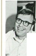
1-p.V Resolution in a Low-Cost 4 1/z
Digit Multirneter
Mooe 3465AtB D1g1tal Multlmeter has a 20-mV full-sea e de voltage range that g1ves a resolut1on of 1 p.V very useful for measunng the outputs of stra•n gages and thermocouples or dnft 1n prec1S10nvoltage sources Themax1murr resolution onac voltage measurements os 10 p.V. on measurements of current (ac or de) IllS 10 nA,and on res1stance measurements,10 mn Open-c,rcu't voltage on the most sens1t1ve ohms range does not exceed 5 volts to prevent damage to most semiconductor de VIces.
Midrange de accuracy 1s ::::0 02% :::: 1 d1g1t The frequency range for ac measurements Is 40 Hz to 20 kHz.
Model 3465AIB IS manual rang1ng w1th aulopolanty and au
tozero. Like Model 3435A, 11 can work with the optional "touch hold" probe to reta1n a measured value on display whenever the pushbutton on the probe IS pushed
![]()
![]()
Roy D. Barker

Roy Barker graduated wuhaBSEE degree from the Un1verS1IY oiOk lahoma 1n 1962 and worked n satellite-tracking InStrumentation and mterowave data 1ni<s before J01n1ng Hew,ett-PacK.ard 1n 1967
At HP,Roy was 1mt:a ly 1nvolved 1n producllon eng1neer ng 'hen be· came 1nvolved 1n IC des1gn and production before oecom1ng sec lion manager for d1g11a1 voltmeters In h1s off hours. Roy ht<es to go cross-country skung,often w1thh1s w1fe and 8-year-old son. and he also en1oys woodwork1ng
Th1s mu111meter IS ava1lable 1n two versiOns. Model3465A 1S 1n a modular cab,netthat IS read1ly comb1ned w1th other modu es for rack mounting or bench stack1ng It has a var.ety of power options, nclud,ng rechargable N1cad battenes w1th 1nterna1
charger. throw-away type-D dry cells (alkaline cells g1ve 60 hours continuous operat1on), or ac Ine The dry-cell vers1oncan also operate on de supplied from hand-held calculator battery chargers
Model 34656 IS housed 1n a streamlined plastic case w1th carry1ng handle It IS powered by ac line and rechargable N1cad battenes
Like Models 3476A and 3435A, Model 3465AIB ach1eves
quality performance at low cost by extensive use of computer aided test1ng, laser-tr1mmed f1ne-line resistors in the attenuator, and a smgle-reference b1polar A-to-O convener.
J]]]]J ]]]]]JJ
![]()

![]()
![]()
VIrgil L. Laing
![]()
Vlfgil La1ng first worked 1n IC de·
velopment upon J01n1ng HP m
1968 subsequently becommg project leader for the NMOS pro cess used lor the 9800-ser,es Cal culator ROMs He ;hendes1gneo a maJor part of the IC used on the
970A Probe Mu wneter Then he became project manager
for the Model 3435A Muoumeter
He has bachelors. master's. and PhD oegrees in e1ectncal en gmeer ng, all from the Umvers1ty of Minnesota Virgil enjoys the Col-
- orado outdoors. go1ng pheasant hun11ng and tak1ng h1s fam1ly on h1k1ng and campmg tnps
![]()
![]()
26
![]()
© Copr 1949-1998 Hewlett-Packard Co.
![]()
HP loloclei3476A.ll Olgrtallolu lmoter
-:Y ,_,. !l•JO'C
.l"'to ,...._"'i 10:JIH
- 7\l.tl....orrt•
rr\P'E r..; ecu £"'· ·fO ol...,.,'i e.-2 :J-;r""
wc:oE "t'CTO'ol • toe ::11 SO K:. a: Hl-
IM"U" 1=£$:St.U..CE tOM
.-q;T O"'ECTDt ''0CN oe..
4C VO..TIETIA
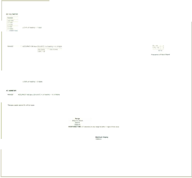
SPECIFICATIONS
lrEAO-.-•? 1:a t.c-.a -'i...-•; lc '1::
J)Jtft_'iSQ6-M--... !lj - 106-o.ee2.J;;)l3Cli NXil·' J!rfj CEJ8t.U.a..A- .)£""'- 122'!.. :lol1'le t:2"'t.
HP llooei3035A Olg•Lal lolwum.,.,
OCVollmeler
..........,.
tew .
•1ft </
s.EWsmvtrr '-"'i...VonJQI)!!.
I»\\V INPVT #fll1t :x: • :»Mart
UHGlHG ;rr-....a
POUJIIrN ...,.....:..Ileal,.....: II'ICI
l""ttt fMOCD:II);........ lOo;illf'¥l!OIII.,oN,!o101" .....'&"91 &o4
_; M07"'S '7 .-.pa :nrQII
ACCU.r.r.on_,..._,
.,.,. _....
2(r-l tJ .Ii """"' _..... t&AUI!u.N0-1• "2A t..!l'•
RA.I,c;MG
· OCrA.•JQQ;.A
ACCIAAC't .,.. e.o..-,fll !":!4y:s- ,_. t 1Co Ma.,....
· tJOI'I
x;t
'-
Q 111n
"""
...,._,
-J
a.CCUP..A.CY , .: c..e• tt-
..... _'(ti"-Df NO r,] l"GGII
""'
0 •.a
0 •.,.
11IJOV
'NIOIJIXI Q.t,Cff"N:) '"' ''
'!"C
lE-hlPIAATV!ifE f;CIEf'ACifHT lil!D !OC &-> .: 30 1o S.S:'C
n'OQ't' ""'.......
· ....en.co.-.,... d'IA:ICale
CCNMONMCIOE "R£JECllOk 'dl.m al'la, -tOall.sou:.. 6J..,
TEWPERATUF£ CQEFf)C[I"KT rO to
OlhrNQ-'10 O'dgl! tKPUl IU.StSlAI'fC£: tO M11 1• tKf:ttfl JYP£ &rJtN "1&1. ·.-...m. 10 qt(U1d
aroc 10 c
$o!I"C
-jiJQY.. fltN,Y' .20;3<U c
VOLTAGE SII.R!nN
W••I'M,I.I,I.I.'I.M,_'\.I,o lll
TCMP£AATVP£ COEF-FICICr :- Oeh-.. rearo; • CIS :ll!jtfl !:
RESIS1410!ro'lh5'
1.11CAPA.CfT "'CE )Q pF
IPU'T PROT£CTION '1000. tllat
PC: AMMETER
RlrNGf ACCUA..ACV .90 O.rt. 20 11C XI !
HOfUitAL MODE RLII..CTlOH All 6J +-u - ' "'-l
EFFECT1Vt COiiM'11! 00£ AEJECTMlftf 'W Wl'IM+!."Cf' 10 CIB 11
SO'to l-It G ,._
A:£SN)HSE. nwr .o 7 « t fl0f'O•op: dt'lA vtiA:I70"•·1J'tS{t! Md
1 •.:end 'or nC/1 f.-got CMofl9ll
DC Current
200mAr•• 2 .,,....
1QOCil'!!"M9t .400'ftV""'
RUPOMst Tlt4f t I MOCI'I:JI O"l anr !3"'Qe W<f''l'l 3 Op;;JI ,.,_ •.&"-•
IHPUl TYPE: f;oet"O """"'f!\111 "' cqon!'!'!On 10 ;r liiC
.:.0 HOA
:110A
tEMPERATURE COE '"FICie.n- .:.fQOS."-t 01 rHO+• l "Dl
lt.I"PEOANCE ._I 5 0M1COI\ ill!
COARENT I'Oli:CTEO 1 S4 M•
.......
:200..A
-'hr
2:!!CMA
SE'N"s"m"V"rJ"Y.l()Qn.l or 200;oA
M•UmumO!•JJJ•w
_!a.9..A
::1999+1\o\
t$!}itr_}.
-1ftf;M
•1999fo!A
Ohmmeter
R•ngM Mtdtfl\.ltft OI•PI•r
· 'iil{S)
2001'1 f99§{)
2o.u 1m•u
20kfi 1 5<9-.11
200..0 t 99 1
2Mu ltoiMO
("I,',...
4.5ti:I021tt1l
( 4... .,
-12 61
2105t,'"(f
•ll!o"-.6·
-
WAXIMUN IHPtiJ Curr..u V.·LH 17U ...a ._. \
RANG-ING Mll!'l\r&l antv
ii'OLARITY:A:..! lly r:ICIO•NI O:st'N)'
4CCUAACY t1y.w 16 lO"Cali$1foAI-fl
201ot.il TI9WMU SvtSinYITY: 10 rwllefll-o-r-: Of' 2011 t"&."'9t-
I"PVT PROTECllOfril t
AAH<l!HG- mlltlc or
TEM"EF!ATUREOOEFFICIE'fT ·t0.CS-c.OI!NOII'IQ•05Cioii"II"C
PEOANCE' 1-1 $ otlm CON l
CU RE._PROTECTEIJ.- 154 lust
OHMMETER
A $plc.mn:teon•
203,10AII:)20mA :.103.Cllnuu::l<'19 -? •,
2:))()o!A :106•.t; •ead"+g-2a;-al
TENPfl'IA7URf CO£FF1Cif.HT 1010 1S"C lt!C Io15CI :.I ::2!1r':JteiiSn;
01dgtlt.J,•c
't'OLTAG!.8UAOEN
'M
ACCUA.ACY (l ';' 1 1!.1£1:.30"C UR' H,
Rl Sp.c:itltltlon•
aou .:ros-. 01 'MdfV - •a d;>l!t
2QO(J-.2Mn ro orfMdlfiCI- 2dOt!S;I
lOMil •1,08 01 tfldo"' - alllitfl
T!MJIEAAl\iAI CM FIC!.!NT 0 15•t •no 3010 $!;•CJ
RANGE
I 1 II
11 •II
110110 liOGooJI ll,QOOIIU
...CC:Uf'IACY ,-wo OlyJ 20 IQ 30"C)
:::!0 6-,-otQ -+ I OQ I
.t(03'!1a!I,Nd.-,g • t dQII!
-!05-.CIIINI)nG I tlgll
M.uomum 11FWII SCI..
20m'<(
• 2.4-Qmv\l
AC Voltmeter
Ft•ng•
lOh-:lt.ll COKAGURAftO""N""2 ._,,. OPEN CIRCUIT VOt..JAGl
CUAAiHT THROUGH UHfC.HOWH;
$pK{"'-tiOft.li
- r oG•••otr no 02doCPfl' e
18'.01 rMO>ng 0 l QIQ!It.JI"(;
TE P£RATI,IA£COEFFICI.EI(l HOO!I• d1e1d"9 02 g1l"C
OPEN CIRCUIT VOLTAG!: 4V
INPUT VOLTAGE PAOTECTION JO Vrm1COIIII!'tvOI.ot luprot&CI ,..t>m
3011 !02.51Wtl'l'll.
Ae COMVE!HIR ••...-;•,. r;g ,.,.. c.ttbf'lltec
A.atiQ!t lO.U 20'00 111{1 200 U 2!:1M!.l
O..t tfll A 51'11A .5 51JA SOC)IA 50nA
AESPON.Sf TIME;0 e MCOI'tdt10wiiNI t o.Qtl.&ro<l 08 tf«<f'ICitl01•1th llifOt
Generel
2V ttv9V
General
At.HOI.HO!. /I..JIOIMIIC AII!!Qf HlliO
oov
1,.1.,1gv.W.,
CALIIRAl'IOH o-1•.n_.u triiCIII IIont llrolll"l"lf"'d I 1 ..... RU.DIHG AAl' 4-<1 t·•tc dta•ndng on l.,ul4 f'
OVEALOAO IOICA TION:Hcti:O'II•I
COWOH TO Q.AOUHD• SOC 1/iuul.+
'*v 1199V
OPEAAnNO TfMPEfllA'rURE 0 tooWC
MAXIMUMI,PUT 17'00Vt• oe•,..;, 10'valltfzmao.
POWER AC •.,,
kt llr&-2SCV
SA MPU RATE. l•eoano.
OV RATI HO eJrtvi" -"EHTAl COHOinoNS . 0 '"' •C'O %-..
POWtR ,.16o\ ·3-'758 ac liM S VA
STANOo\Ail 104·12'1V 54-U Hz
OPTIONOOI Cl&-106\1 S4-6& J Of'TJON 002 ettr> 1o6V ..8-5-1HJ OPTICIN 003 1 ·1lOV ,..S.$4 Ht C»"TION 001 20!-:?SOV ll!I-$A H1
J.4768 UAfTElii.ES t ' "•roe"".,.' eaarnNI'I'I wo-e 11:te TYJ;> e!eeo't bnuoOO«HIIIIMtJ nMe , ,.no,.,,,, ..o.u.: t.!lir!••• 8 ••• 25'C Typalbll111lfy c:!tMgi"'j f>IMI 14 "'Vt II 0'5 C WTI! "' lr\o"''tr.' Wrt! It
luekla cnar m-II\Sir"o m•m 1)1'1
stH&mvrrv·100..v on )!)()r!V ....
Af'(<Jb'AUio-r•bc: Of rlllll.;ll
4CCUIII:ACY t<'M!"d r0!'20CJ19b I '(eal t51D-Ca!M
R•no- 5p e he1$10MI
lO 1-i.t-$10 1-!1 -II 5"o Ql r•!I<J.ng ) IIQ•"
S01-:1:-20H1t -I:JJ":tOfr•acJn; 1 1",
o:H, r-tOQI\Ht p..., ot rNOr>g - 11'1 rl>:l•l•t
r!¥PfRATUFIE COf,IK;'IENT !0 10 15'C INI 3G IO 55'C)
(0 O'"'o ul •M+S- 02 cigt! C
INPUll..PEO•H<:E 5 llofil:tF
1-fUMIOfTYt Djoi ·15 It> '!tC
4:8--4<11)
8An£A'f ,.;:n•ogqr.e !uo tQO 10 r.ov,_ lfiO'Io l"' (OIIIIt ()9W/ll)Qll'!
""I'll '"' ttrerv• Attmll ">15 hOwfl OC*lllnQ ll '*"" il\1'10
'TOTAL l 'fFii!,.MENT 11QW£A Dr$SIPA!EO ... C)l'lly lMUIJ < 'tl ct'.ir'QII'
e ..an.
OIMfHSIO NS- 2361 ,,1"1 w dll i.S• Mrr 1Q ' n•lll'l"' d :l !936•
3'. IO't 'IC,.. 0::1002.2l0·SCSf..-2'd71'"1mii:II+•J;•10'1t'll
WEJG.Hl. t.a• •!i 1Slb &a ,1 Opi(X)I I&*(4 l 0 1
PRICf.S!NU..!i .tltiJ!..A...00 •tlhOOIQI1f\'l.. Opl 0011 11..1&! Rtci\·111110-
•IMeh.C-0o1 ooa 1•e '• :10'1,... ol'!l.,,,lltM$l5 J llZA rOi.IVI*' oiOP oo.
![]()
![]()
Joe E. Marriott
A 1969 graduate of the University of Utah (BSEE). Joe Marnott JOined HP that same year, going to work on the Model3403A True rms Voltmeter Returntng to HP followtng a tour of duty With the National Guard, Joe contnbuted to the 970A and3465A Voltmeters. While working on the 3476A/B
Joe became pro,eclmanager. Along 1he wa y, he earned an MSEE degree at Colorado State Un1vers11y inIhe HP Honors Co-op program Marned and with a

2-year-old oaughter, Joe cross- country skts. hikes. plays volleyball. and occasionally does some photography

![]()
H. Mac Juneau
Mac Juneau jotned HP in 1967. go1ng to work on the Model 3480A Oig1tal Voltmeter and !hen on high-speed A-to-O converters as proJect manager For three years. Mac was product assurance manager w1th time out as proJeCt manager for the Model 3476A Mulllmeter He IS now manager of the HP Loveland fac1ililes IC lab He has a BSEE degree from Swarthmore College (Philadelphia) and MSEE and PhD degrees from the University of Minnesota. With
children 8 and 5, Mac contnbuted to a school playground destgn He also does some woodwork Ing and creates welded sculptures
![]()
27
© Copr 1949-1998 Hewlett-Packard Co.
SPECIFICATIONS
Renget
tiP ModelJ.465AIB DigitalMuiUmeter
OC Voltmeter
MUI"'Oilpte
Rlllif•
20otl
,..,
2001:fl
2000,0
20t.IO
Ohmmeter
M.,u.n.n,.u.mOltpley
19 999
1&999
1999..9
TEJtp£AATURE COEFRCtEN(lO"C :o WCJ
.:OOQ!.o..ot rN.Oo'IQ .:. 2dgil.
INPUT tMPEDA.NCE• I Mfi••-<100 pF
INPUT TYP!.! nCNIIII"Q,500'/tnal:il'nu( Dn;r!Qrl to QIOI.ftO
OVERLOAD PAOTEOTJQN; <It, 600V tNUF .e. 5/JrN tn11 BQO'J Clf:'6
AUP S£ nMEl 5S&COMd1IO W'!hlrl I d91
.:-20mV
.:200m\!
=-2'J
.....
SEH.SJTIVIn'· 10I"'! OIIft'l on ,
IHPllt ltAOrt-enoN:35CIV 101: • .11t:'f250V rms
ve•
AC CLirrent
...A1mum Dlo'plly
19999
m 19.999
ACCYRAC'f C1
23"C - 5"C@ fl1l
_-2,0_0V,
199119
1000.0
Fl..,g.
20011
2'<llbfV2 MO
SpKlfltwtioa•
...t)_ offN(YIQ-201Q!IS
.:.O. cl tU01l!f· l (llgll
1.999
.1.9.9.9.9.
SEKSil1VITV: 1 "11>00\-olt 0.11ot.w1 ID1'191
MAXtMUM NPUT:10001/ll'IA.ll ck and po:ak oc
POl.A.RITY Au tlbt:e!IV !>lt1ICI d•spW!yeo.
ACCURACY (t yeti 23C d'C al 95R' HI
R•no•
200mV""11"1'r"u 200V
lOOOV
fEMPlA,t.TlJRf COEFFtC1EHT iO'C lo 60'C).
oooo:;. Oi'ee.oifiO"C.
INPUT R.ESISTANCL
VInnt2V
20V 11""..1 ,OOOV
Spetlt\.aiJon•
.:0.03<;. o!fMr:ling :. 2 dg':s
.:002'1\. 01 re&di"Q :. 1 digl
o02Sol rtedng - 1 0.011
51)telf1Ct11101'11
•10''11
10M()- 1"-
.l::! MU
TEMPERATURE COEFFICI£1'n" lO'C 10 5Q"Ci
Rl1'191
0011111111; 2 M!!
20 on
(;ONRQURATIDN: 2·.wile OPENCfRCUfT VOllAGE: c 5V m.v. CUfiAtHT THROUGHUHKNOW'N:
Rang• Oun•M
2>0 ,,..
20,0 ..
<ooo•o .....
..MU
:.0 1...o!·eldlng"' 1 a.:;u
c.uo'"
"0001!'r.VtNd!'QtC
:()of r ingf"C
SEJ.IStnVITY:IOi""AOn stt5rogt.
MAXIhW M IN'PUT::CA lr01n '"250Vs.ouo:ee (l.IM ed) ull.-cal tto tOJd-U
oeereUII'lg line ; so-.tvl!eale at 2011Hz Ot\llfWtlst3raoges 2kHt ma..on.
200mA •ai"Q" 1 kMt mil:" 00'1 2000.:M 111rr,a-
ACCURACY 1 )'tl&f,Zl'C ..- S"C:@ 95 RH>
"!0.l,l N0!"'9
:1Sd'9ils
"()6 lUGnQ
"-0 4.. teadn; -$ O IIS
INPUT TYPE:1\ollll$0QY miP,Imll"l (l(ltmiOf'l lO 0JOUf'ld
NORMAL MODI! f'!:J!CTION -.eo UB i150.·'60 Hl .:- •"•
EFFECTIVE CO.htMOI<t Jit'OO£ J:ltJECnO.. i' IIJ) Ufltli!iii!Cj) :•120 dB 81
S0.'60Ht. ::-.1.._
RESPONSE l1ME• 1tetQnCI 10 wlli'lt di;tl
RESPONSE n M!::2 4nrort0!110 " 1 dg1.
AC Voltmeter
AC COHVERTER< avl!r&a$ r$$DOI!d.ng, tmc. catbrnltQ
......,..
•61Jg!!!
20nA
.000.....
A-l.llt.g.••
'-.::"2-0"n-' ·
DC Current
MeJImI u:mD•I plty
I!J999
1.9r-99
19 .99 9
Aange.s
200mY
tv
>av
"">V
"'""
S£N$1TIVITY: tON; on IO'ft-811 tti"We
Maldmum Olspl•
199.99
19!KI9
19U9
500.0
T!.MP£RATUR£ COEfFJCI£1'fT (C7C 10 SO"C). .e-O ou..qf f'8i<!!I'!QI C
VOLT.A.E 8URDEN:
,A RANGE: <700mV It
At.l arr1ER RANGE$ ...- 50mV II RESPONSE 1\hll:! 5 toton4llO :flin 1 OIQ!l
,,....,.
1mil
M .U MUM INP"UTfut teA to- 10 UU doae tlf'911M!()50ot lull at
20 kKt OJCQIIPI 5QOV '411108 has 2·kHz m11:11i1T1wn lnaqt.oncy
S"C@ 9S'<c AH):
SENSfflmY: tOnA 'CII"' t1wes.1t11ngt:
MAXIMUM INPUT: 2A fllom <2'50V ao.nte (lUte ltd)
POLARITY: AVIOITI IIy $$n&ed and <hP )'911
ACCUAAC'f 11 year, 2:]C· 6'C al 95.._, AH)·
Spetll!utJona
200uA, 2mA -o.07o eetll:lng I 11911
ACOUBAQ't' (1 r-¥.1J•¢ ::
IOAMt
General AEADINO RATE:21? •&&Snp p!lf 5eoand. OVSALOAOINDCI ATION:CSI&;:I.ay &!!ks KUMIDtT'f RANGE:ft 40'0
OPfAAllNG Tll:MPtFtAtURE: O'C io ..55'C (nio..fok&CI!I'II!..rl Wrlllt n
O'C to ...-40'C)
W'tiOJiT; 2J)4 kQ (• t>t.., 8
20mA
ZOOmA,2000tnA.
TEMPERATURE COEF-ftCJENT f(YC 10 WC)
,...,...
2mA,1Qmo\
OOCmA,2000mA
VOLTAGE 8UAOEH
HIGHl RANGE 7V FS.
Al.lOTHE.A ANGES·o:25QtnV FS RESPONSE11ME: 1 ' II lo ....uhln 1 dg.t.
:011--.ol(,.,&ding.:. 16911
:-0.Of tea&ng 1 o
SP"Ific:tUons
;:;0 005'01 rNd"Q"C
--:OOQ.t,Oi t tl13(1if'lQt"'C
-t>OllloOS tt ;ICIII"'IIJ!"C
lnpul
Volt.ge
Ft ncy .:.o.ts'te&6f19 .u,1.5 rt»no
.:.5(%1 .:.SGglls;
' '"'
500V
0Ur £N510HS; 101 6 f!'lfl'l h•gt'l Jt 212.7 ml"l wnclte ""' V9 • rm 09$9 ('.ot 8-3•8
><. 1-lnl .t
POWER:aellle,6&-121V.1 4!JOV;4SJ. I-fl
BATTERIES·l lla!peablo llltk mlu-m &lilnditd
Contlruoua. Ol) .g lime !rom IIA Wrge ll 6 tlovf"l- Rechait'"' ..,.... ,,8
W'll'lln!IIV!III'II otl Tld.\e chefQ.e "Min1nstrumtrl1on
OPTI0N(l(l:2:fyplil 061(,a,IIN'Itl'y otii6(U·2-eellt 111 ElliCipeJ. 1)0 I'!OI.JISOcn!lllUOI4
Ae 111 '3"C l es f&Ceotai:::lt '10 us.- MOC!!'l B2002A oallory •lrrulatof
(820CflA nc(lntlllc:IIGI
JCE )NU.SA. , I
3466A, $630: ()Q( 001 ec line 0111y -s20. - 002, -$105
3.t.!i6B,1500. 34112 TOIRI·Hold Pto1>t $&0.
...._NUFACTUAIHGDIVI$10N: t.OVel..ANO IN$TAUMEH'T DIVISION
81S Fo;meorntn Slrett S.W.
Lch•Ned, CoiQf'ac;tc) aG537 U.S.A-
Hewlett-Packard Company, 1501 Page Mill
Road, Palo Alto, California 94304
FEBRUARY 19n Volume 28 • Number 6
TechnicalInformation from the Laboratories of
Hew!ett.Packllrd Company
Hewletl-Packard Ce llaJ Ma ng Dep;;rtmc l
Var Heuven Goedharilaan 121
Amsrelveen-1134 The Ne!herfanos Yokogawa-Hewlelt·Packaro Lid , SMxJya-Ku Tokyo 151 Jaoan
EditorialDirector o Howard L. Roberta
Managing Editor • Richard P. Dolan
Art Director,Photographer • Arvid A.Danlelaon
Illustrator • Susan E.Wright Admlnlatratl,.Services, Typography • Anne S.LoPrutl European Production Manager o Tlna Eysten
CHANGEOI-AlJUHcS
Bulk Rate US Postage Pard
Hewlett-Packard
Company
To change your address or delere your name from our mali ing lislplease send us your old addresslabel(11peels off) Send changes to Hewle·Packard Journal. 1501 Page Mill Road,Palo Allo, Cantornia 94304 U.S.A. Allow 60 days.

© Copr 1949-1998 Hewlett-Packard Co.