This site may not get much updated any more, last update 17/06/2003
As long as I worked on the project I placed many updates, but now the final PCB is ready so I leave it to this.
The final circuit is at the bottom of the page, in the first part you can see how I got to it. There are two minor problems you could encounter. The crystal is running on (too) small capacitors all my junkbox crystals worked fine, but you might find they don't always start. I encountered an other small problem that was a leaky 7400, it produced a tiny 597 kHz component in the USB mode, it makes a nasty whistle. It seemed the 5/0 V line was not pulled low enough. After changing this, it sounded lots better, but keeps having a small whistle. It seems the 7400 itself was just a little leaky, a newer SN74LS00 proved to do a much better job.
last update April 4 2004.
How it all started.
The circuit described here generates 597KHz for carrier reinjection so you can hear LSB signals on for example the Sailor R1119 or other receivers which use 600KHz reinjection for USB.
This circuit can also be used for S1303 or similar transmitters which use 600KHz for USB generation to make LSB.
One thing has to be kept in mind, due to the 3KHz signal difference also the RX/TX frequency is off by 3 kHz
The solution to this problem seems to be the circuit on the bottom of this page, on this moment I tested this circuit on both my receiver and exciter, it looks like it's working fine. I made several contacts on 40m with good reports and on right frequency (display readout = TX/rx QRG).
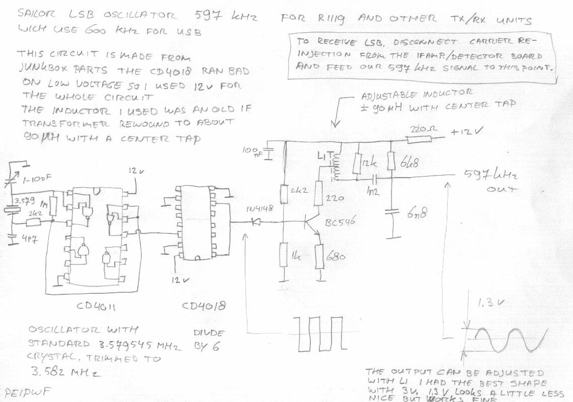
This is the circuit for 597KHz, I made it out of junkbox parts, so I know there might be improvements, please let me know if you have a nice idea.
Note, You don't need the sine shaper part of this circuit if directly attach the square wave output to the anode of Diode 102 in the divider module.
If you want to do this, cut loose the diode at the anode side (connected to pin 5 of IC111 74LS390) you van make it switchable or whatever you want. Be careful with this mod, you should try to damp the output of your 597KHz output, because it is well over 5V.
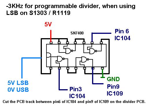
Use this circuit to make your frequency 3KHz lower to compensate the 600-597 kHz difference.
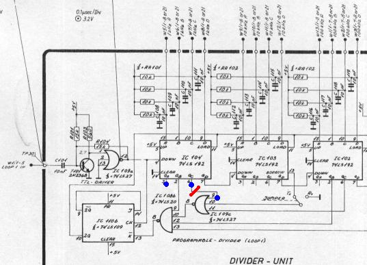
These are the connection points in the sailor schematic.
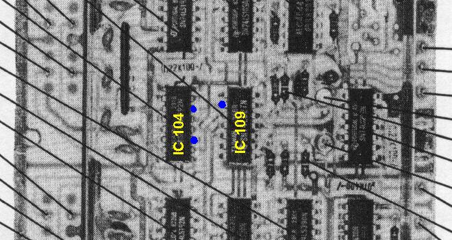
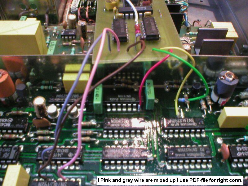
Connection points on the PCB.
This is the "final" circuit!
After some weeks experimenting I made this PCB, it generates 597 kHz and changes the programmable divider. so we get LSB signals and correct frequency read-out.
PDF-file of the circuit/board/layout!
NOTE! for the 7404 in the circuit you HAVE to use a SN74HC04 or SN74HCT04 the 7490 and 7400 can be a quite ordinary SN74LS90 and SN74LS00, I had used an old SN7400 bot it had some problems switching 597KHz.
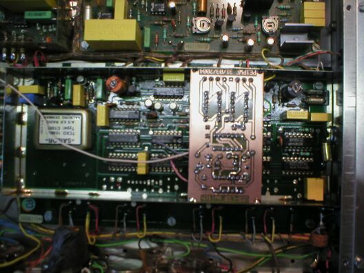
This is the circuit board connected, note the ground is not being used as I solder the board into the tin "fence" in the divider board.
For switching 0/5V I used the mode switch on "TELEX" I used the 18V of this switch and a voltage divider 1k5/270ohm to switch 0/3V (3v looks enough like 5V)
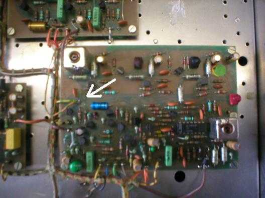
The PCB track between pin6(IC104) and pin9(ic109) has to be cut. this is on the bottom side of the PCB, so I just cut pin9 just above the PCB.
The small blue diode in the picture is cut at the IC-side this IC-pin connect to 600KHz input of our PCB, the loose end of the diode connects to 600/597 kHz out.
The PCB soldered in place.
As I already told, I used the "telex" wire to switch to LSB.
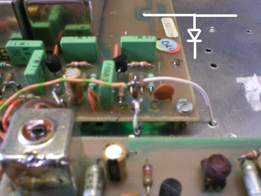
The Orange/green wire was 18V when switched to telex, this is used to silence the receiver when in telex mode. I took this wire and mounted this on a 1n4148, which is mounted on the USB wire in the picture below. the same 18V (white wire) goes to my USB/LSB switchover unit and provides the 5V to switch my circuit to LSB.
Remove this orange/green wire.
Mount the orange/green wire here using a 1N4148
Naturally you could use a simple toggle switch to provide 5/0V (you should pull-up and pull-down to keep the wired from floating) this is how it is done in the exciter. You can use exactly the same circuit and add a switch on the left-side of the frontpanel to change usb/lsb mode.
Today I got the sailor circuit! this uses a 11.94MHz crystal divided by 20 to get 597 KHz.
73'
Edwin PE1PWF