|
Parallel port
basics:
In
computers, ports are used mainly for two reasons: Device control and
communication. We can program PC's Parallel ports for both. Parallel
ports are mainly meant for connecting the printer to the PC. But we
can program this port for many more applications beyond
that.
Parallel
ports are easy to program and faster compared to the serial ports.
But main disadvantage is it needs more number of transmission lines.
Because of this reason parallel ports are not used in long distance
communications. Let us know the basic difference between working of
parallel port and serial port. In serial ports, there will be two
data lines: One transmission and one receive line. To send a data in
serial port, it has to be sent one bit after another with some extra
bits like start bit, stop bit and parity bit to detect errors. But
in parallel port, all the 8 bits of a byte will be sent to the port
at a time and a indication will be sent in another line. There will
be some data lines, some control and some handshaking lines in
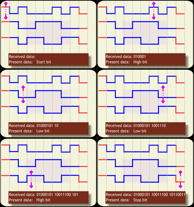
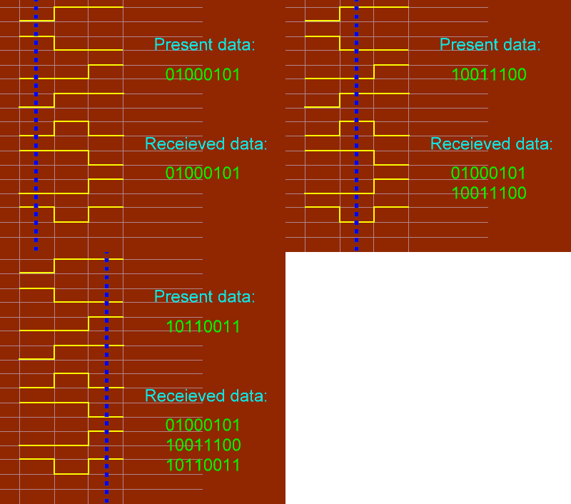
parallel port. If three bytes of data 01000101 10011100 10110011 is
to be sent to the port, following figures will explain how they are
sent to the serial and parallel ports respectively. We can
understand why parallel port communication is faster compared to
that of serial.
|
Serial port: Data transmission
will be bitwise, one after another.

figure
1.0
© electroSofts.com
|
For more detail on RS232 serial port programming
and connections, read our article "Serial Communication using RS232
port". This article explains serial port
programming with example source code PC to PC chat in DOS with
direct cable connection.
electroSofts.com will soon bring you an
article on serial port programming in
Windows. |
|
Parallel Port:
Data transmission is byte wise:
Whole byte at a
time.

figure 1.1
© electroSofts.com |
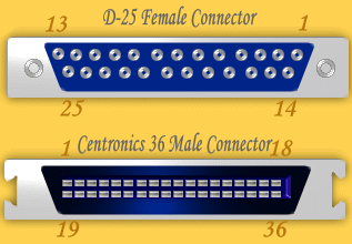
In the PC there will be D-25 type of female
connector having 25 pins and in the printer, there will be a 36-pin Centronics connector. Connecting cable will
combine these connecter using following convention. Pin structure of
D-25 and Centronics connecters are explained bellow.

figure
1.2 |
D25- Pin
Number |
Centronics 36 Pin
Number |
Function |
| 1 |
1 |
Strobe |
| 2 to 9 |
2 to 9 |
Data Lines |
| 10 |
10 |
Acknowledgement |
| 11 |
11 |
Busy |
| 12 |
12 |
Out of Paper |
| 13 |
13 |
Select |
| 14 |
14 |
Auto feed |
| 15 |
15, 32 |
Error |
| 16 |
16, 31 |
Init |
| 17 |
17, 36 |
Select In |
| 18 to 25 |
18 to 30, 33 |
GND |
| - |
34, 35 |
N/C |
Table
1.0: Pin numbers and functions
Now let us know how communication between PC and
printer takes place. Computer places the data in the data pins, then
it makes the strobe low. When strobe goes low, printer understands
that there is a valid data in data pins. Other pins are used to send
controls to the printer and get status of the printer, you can
understand them by the names assigned to the pins.
To use
the printer port for applications other than printing, We need to
know how ports are organized. There are three registers associated
with LPT port: Data register, Control register and Status register.
Data register will hold the data of the data pins of the port. That
means, if we store a byte of data to the data register, that data
will be sent to the data pins of the port. Similarly control and
status registers. The following table explains how these registers
are associated with ports.
|
Pin No (D-Type 25) |
SPP Signal |
Direction In/out |
Register.bit |
|
1* |
nStrobe |
In/Out |
Control.0 |
|
2 |
Data 0 |
In/Out |
Data.0 |
|
3 |
Data 1 |
In/Out |
Data.1 |
|
4 |
Data 2 |
In/Out |
Data.2 |
|
5 |
Data 3 |
In/Out |
Data.3 |
|
6 |
Data 4 |
In/Out |
Data.4 |
|
7 |
Data 5 |
In/Out |
Data.5 |
|
8 |
Data 6 |
In/Out |
Data.6 |
|
9 |
Data 7 |
In/Out |
Data.7 |
|
10 |
nAck |
In |
Status.6 |
|
11* |
Busy |
In |
Status.7 |
|
12 |
Paper-Out / Paper-End |
In |
Status.5 |
|
13 |
Select |
In |
Status.4 |
|
14* |
nAuto-Linefeed |
In/Out |
Control.1 |
|
15 |
nError / nFault |
In |
Status.3 |
|
16 |
nInitialize |
In/Out |
Control.2 |
|
17* |
nSelect-Printer/ nSelect-In |
In/Out |
Control.3 |
|
18 - 25 |
Ground |
Gnd |
|
Table 1.1: Pin directions and associated
registers.
* Pins
with * symbol in this table are hardware inverted. Than means, If a
pin has a 'low' ie. 0V, Corresponding bit in the register will have
value 1.
Signals
with prefix 'n' are active low. That means, Normally these pins will
have low value. When it needs to send some indication, it will
become high. For example, Normally nStrobe will be high, when the
data is placed in the port, computer makes that pin low.
Normally, data, control and status registers will have
following addresses. We need these addresses in programming later.
| Register |
LPT1 |
LPT2 |
| Data
register (Base Address + 0) |
0x378 |
0x278 |
| Status
register (Base Address + 1) |
0x379 |
0x279 |
| Control
register (Base Address + 2) |
0x37a |
0x27a |
Note:
All the parallel ports do not have bidirectional capability. Earlier
parallel ports had only output enabled in data pins since printers
only inputs data. But latter, to make parallel port capable of
communicating with other devises, bidirectional ports are
introduced.
By
default, data port is output port. To enable the bidirectional
property of the port, we need to set the bit 5 of control
register.
To know the
details of parallel ports available in your computer, follow this
procedure:
-
Right click on My
Computer, go to "Properties".
-
Select the tab
Hardware, Click Device manager.
-
You will get a tree
structure of devices; In that Expand "Ports(Com1 &
LPT)".
-
Double Click on the
ECP Printer Port(LPT1) or any other LPT port if available.
-
You will get details
of LPT port. Make sure that "Use this Port (enable)" is selected.
-
Select tab
recourses. In that you will get the address range of port.
To start
programming, you will need a D-25 type Male connector. Its pin
structures can be found in the connector as follows:

Programming the printer port in DOS:
To start
programming the port, we will use DOS. In DOS we have commands to
access the port directly. But, these programs will not
work on the systems based on Windows XP, Windows NT or higher
versions. For security reason, higher versions of the windows
does not allow accessing the port directly. To program the parallel
port in these systems, we need to write kernel mode driver. In the
part II, I am going to explain about programming the parallel port
in windows XP. If you want to run the same program in Windows XP,
For studying you can use the technique
that I have posted in this forum.
When we
want to find out whether particular pin of the port is high or low,
we need to input the value of corresponding register as a byte. In
that, we have to find out whether the corresponding bit is high or
low using bitwise operators. We can't access the pins
individually. So, you need to know basic bitwise
operations.
Main
bitwise operators that we need are bitwise AND '&' and bitwise
OR '|'. To make a particular bit in a byte high without affecting
other bits, write a byte with corresponding bit 1 and all other bits
0; OR it with original byte. Similarly, to make particular bit low,
write a byte with corresponding bit 0 and all other bits 1; AND it
with original byte.
In Turbo
C, there are following functions used for accessing the
port:
-
outportb( PORTID, data);
-
data =
inportb( PORTID);
-
outport( PORTID, data);
-
data =
inport( PORTID);
outport() function sends a word to port, inport() reads a
word from the port. outportb() sends a byte to port and inportb()
reads a byte from the port. If you include DOS.H header, these
functions will be considured as macro, otherwise as functions.
Function inport() will return a word having lower byte as data at
PORTID and higher byte as data at PORTID+2. So, we can use this
function to read status and control registers together. inportb()
function returns byte at PORTID. outport() writes the lower byte to
PORTID and higher byte to PORTID+1. So this can be used to write
data and control together. outportb() function write the data to
PORTID. outport() and outportb() returns nothing.
Let us start with
inputting first. Here is an example program, copy it and run in
Turbo C or Borland C without anything connected to parallel port.
Then you should see data available in status register and pin
numbers 10, 11, 12, 13 and 15 of the parallel port. Pin 11 (active
low) is 0 and all other pins are 1 means it is OK.
/* file:
ex1.c
by HarshaPerla
for electroSofts.com.
Displays contents of status register of parallel
port.
Tested with
TurboC 3.0 and Borland C 3.1 for DOS.
*/
#include"stdio.h"
#include"conio.h"
#include"dos.h"
#define
PORT 0x378
void main()
{
int
data;
clrscr();
while(!kbhit())
{
data=inportb(PORT+1);
gotoxy(3,10);
printf("Data available in status register: %3d (decimal), %3X
(hex)\n", data,
data);
printf("\n Pin 15: %d",(data &
0x08)/0x08);
printf("\n Pin 13: %d",(data &
0x10)/0x10);
printf("\n Pin 12: %d",(data &
0x20)/0x20);
printf("\n Pin 11: %d",(data &
0x80)/0x80);
printf("\n Pin 10: %d",(data &
0x40)/0x40);
delay(10);
}
} |
To understand bitwise operations: you want to
find data in pin 15, value of (data & 0x08) will be 0x08 if bit
3 of register is high, 0therwise.
|
bit
no. 7654 3210
data : XXXX
1XXX
& with : 0000
1000 (0x08
)
-> 0000 1000 (0x08 -> bit 3 is high
) |
bit no. 7654
3210
data : XXXX 0XXX
& with : 0000 1000
(0x08
)
-> 0000 0000 (0x00 -> bit 3 is
low) |
We will
use the same logic throughout the article.
Now,
take a D-25 male with cables connected to each pins. Short all the
pins from 18 to 25, call it as ground. Now you can run above program
and see the change by shorting pins 10, 11, 12, 13 and 15 to ground.
I prefer using switches between each input pins and ground. Be
careful, do not try to ground the output pins.
To find
out the availability of ports in a computer programmatically, we
will use the memory location where the address of port is stored.
| 0x408 |
0x409 |
0x40a |
0x40b |
0x40c |
0x40d |
LPT1
low
byte |
LPT1
high
byte |
LPT2
low
byte |
LPT2
high
byte |
LPT3
low
byte |
LPT3
high
byte |
If you run the the following code
in Turbo C or Borland C, You will get the addresses of available
ports.
/*PortAdd.c
To find
availability and addresses of the lpt ports in the computer.
*/
#include <stdio.h>
#include
<dos.h>
void main()
{
unsigned int far *ptraddr; /* Pointer to location of Port
Addresses */
unsigned int
address; /* Address
of Port */
int a;
ptraddr=(unsigned int far *)0x00000408;
clrscr();
for (a = 0; a < 3;
a++)
{
address =
*ptraddr;
if
(address ==
0)
printf("No port found for LPT%d
\n",a+1);
else
printf("Address assigned to LPT%d is 0x%X
\n",a+1,address);
ptraddr++;
}
getch();
} |
Next we will go to check output pins. To check the output, we will
use LED's. I have driven LED's directly from the port. But it is
preferred to connect a buffer to prevent excessive draw of current
from the port. Connect an LED in series with a resister of 1KW
or 2.2KW between any of the data pins(2 to 9) and ground. With that,
if you run the program given below, you should see the LED blinking
with app. 1 sec frequency.
#include"conio.h"
#include"dos.h"
#define
PORT 0x378
void main()
{
while(!kbhit())
{
outportb(PORT,
~inportb(PORT)
);
delay(1000);
}
} |
I will
stop this part here itself. Next part of this article is now
ready. In the PART 2, you will learn programming the parallel port
in VC++. PART 2 is designed for the beginners of VC++. Click here
to Read part 2.
Part 3
is having the example using LCD module. There we are going to learn
connecting LCD module to parallel port. Read part
3.
Also Read...
-Programming
the Parallel Port(PART 2): with VC++
-Programming the
16x2 LCD module with Parallel Port: Example 1
-PC Based Game
show/Quiz buzzer: Interfacing project example 2
-Serial
communication via RS232 with C
-Links to
port programming related articles in other
sites |