Gecko Error/Reset Controller
The Gecko G320 and G340
controllers are fabulous devices, but have one minor little annoyance - the
Error/Reset pin. The operation of this pin is somewhat confusing, and the
usage even more so.
The newest version of the Gecko 3x0 drives ease the use of this pin by
allowing a person to wire all the pins in a system together, but this is still,
in my opinion, an incomplete and inflexible solution.
Looking at the various circuits available from a number of sources, I decided
that none of them precisely suited my needs and so decided to create yet another
design. Considering that the problem was mostly one of logic and
only partly electronics, I decided to use a microcontroller.
My design goals were these.
- Automatically provide the 5 second reset required at powerup.
- Fault all the channels should a single active channel fault.
- Provide a means to disable all the motors without having to resort to a
poweroff.
- Provide a means to disable a single channel without disturbing the the
fault detection logic.
- In the event of a fault, indicate which channel caused the fault.
- Allow an EStop input to disable the Geckos
- Allow an EStop input to disable the motors. ( Not the same thing as #6 ! )
- Send a signal to the controlling PC should a fault occur.
- Automatically control relays for both safety reasons, as well as providing
dynamic braking capabilities.
At the end, I came up with a reasonably
simple design that does all of the above, which I called the GERC, for Gecko
Error Reset Controller. Information on this original device, including all
that's required to allow a person to build their own from scratch, can be found
here.
After a couple of years, and based upon user requests, a couple of small
enhancements were made, resulting in Rev 2, shown below. These
enhancements allowed the GERC to send an EStop signal to almost any device via
the contacts of a SPDT relay, and uses screw terminals for electrical
connections.
GERC R2
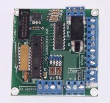
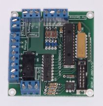
(Click either image for a larger view.)
A complete manual, including schematics, can be found here.
GERC_RLY
The GERC requires, at a minimum, an
external source of 5 volts to power the microcontroller. To make full use of the
board's capabilities to safeguard against a "crash", external relays, diodes and
power resistors are also needed, as well as an additional voltage source to
drive those relays. So a second version of the GERC was produced, the
GERC_RLY, that contains all of the above in a single board.
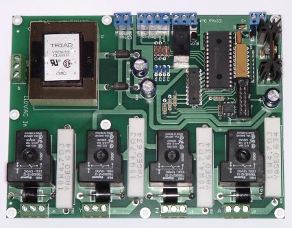
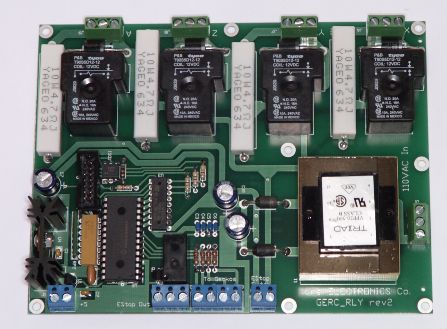
(Click either image for a larger view.)
A complete manual for the "relays included" version, including schematics,
can be found here.
Differences between the GERC and GERC_RLY
The difference is that the
GERC requires a person to source relays, diodes, braking resistors and a power
supply, and then wire it all up. The GERC_RLY saves a person all the
trouble, but is of course more expensive. Other than that, there really
aren't any differences. Both use exactly the same parts in the logic
circuitry, including exactly the same code in the microcontroller.
Human Interface
Individual axes are enabled and disabled, and the whole
device reset, from switches attached to a PCB that is itself normally mounted to
the front panel of your controller. That same PCB also has LEDs on it
supplying status messages. An LED glowing solidly indicates an enabled
axis, a single LED blinking rapidly indicates that the Gecko controlling that
axis has faulted. All LEDs blinking very slowly indicates that the GERC is
resetting the Geckos, and all LEDS blinking very rapidly indicates an EStop
event has been detected (either the "Big Red Button" has been pressed or a limit
switch has been activated).
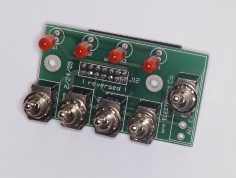
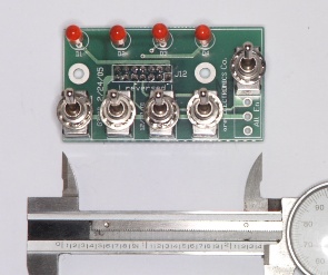
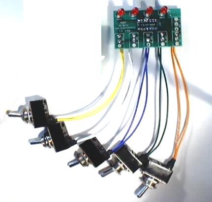
The switch board is available as shown above, with 1/4" mini switches
soldered directly to the PCB, for a nice, compact unit (perhaps remotely
connected to the main controller) or with conventional 7/16" switches connected
via 6" of colour-coded wire, as shown below.
Back to
Index Pricing


