|

|
Features |
-
+18£+80VDC, 0£20A,
20£400W
-
PID
feedback servo drive
-
Feedback resolution X4 encoder line
count
-
Lock
range +/- 128 count following
error
-
Opto-isolated step and direction inputs
(differential)
-
Small
size
-
Over-current, short-circuit
protection | |
| Introduction |
|
The DB810A is
a digital DC servo driver developed with CPLD and high
efficient MOSFET technologies. In position control,
it¡¯s easy for the end users to change stepping drivers
to the DB810A without changing control systems, because
its input command is PUL/DIR signal, which is compatible
with that of stepping drivers. In low power motion
control applications, performances of DC servo systems
using the DB810A are better than those of digital AC
servo systems in velocity, precision, noise, stability,
or at least as good as those of digital AC servo
systems. However, the cost of the DB810A stays at the
price line of stepping driver, namely far lower than
those of AC servo drivers. |
| Applications |
|
Suitable for
a wide range of equipments and instruments such as mini
type engraving machines, jet-ink machines, etc. It
performs better in equipments desired for low noise,
high velocity and high precision. |
| Electric Specifications
(Tj=25¡æ) |
Parameters |
DB810A |
|
Min. |
Typical |
Max. |
Unit |
|
Output
current |
0 |
- |
20 |
Amps |
|
Supply
voltage (DC) |
18 |
- |
80 |
VDC |
|
Logic
signal current |
7 |
10 |
15 |
mA |
|
Pulse input
frequency |
0 |
- |
500 |
KHz |
|
Isolation
resistance |
500 |
- |
- |
M¦¸ |
|
Current provided to encoder
|
- |
- |
50 |
mA | |
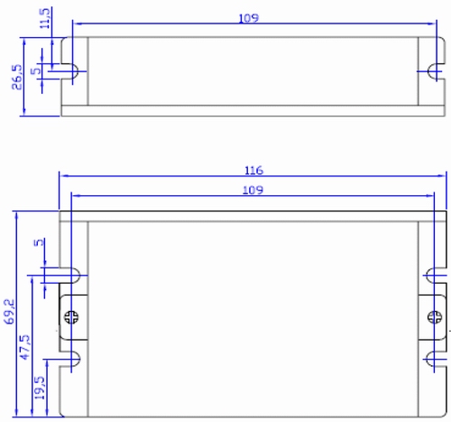
| Mechanical
Specifications (Unit: mm, 1 inch=25.4
mm) |
|
Figure 1:
Mechanical dimensions |
| Connector Configuration
|
|
Pin
Number(Term.) |
Function |
Pin
Number (Term.) |
Function |
|
1 |
PUL+ |
9 |
E+5V |
|
2 |
PUL- |
10 |
EGND |
|
3 |
DIR+ |
11 |
ERR/RES |
|
4 |
DIR- |
12 |
Motor+ |
|
5 |
EB+ |
13 |
Motor- |
|
6 |
EB- |
14 |
+18 TO
80 VDC |
|
7 |
EA+ |
15 |
PGND |
|
8 |
EA- |
|
|
|
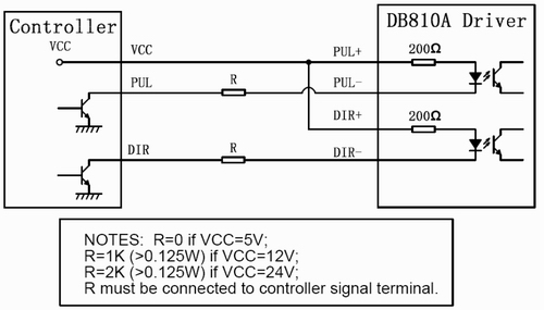
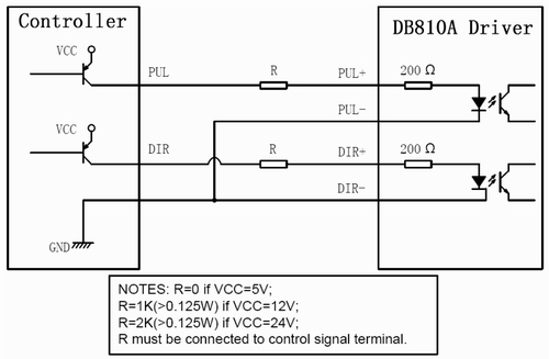
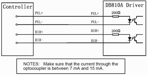
| Control Signal Connections
|
|
Figure 2:
Connections to open-collector control signal
(common-anode)
Figure 3:
Connections to PNP signal (common-cathode)
Figure 4:
Connections to differential control signal
|
| Typical Connections |
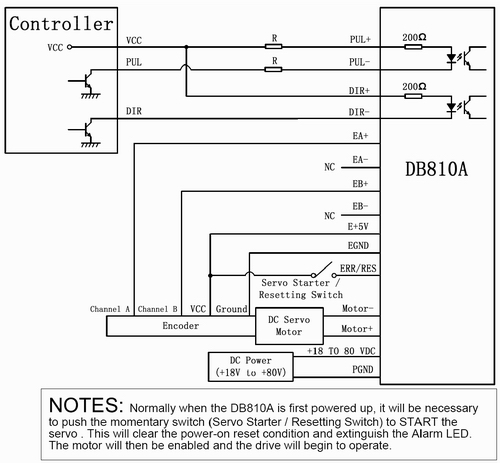
Figure 5:
Typical connection (Open-collector control signal and
single-ended encoder.)
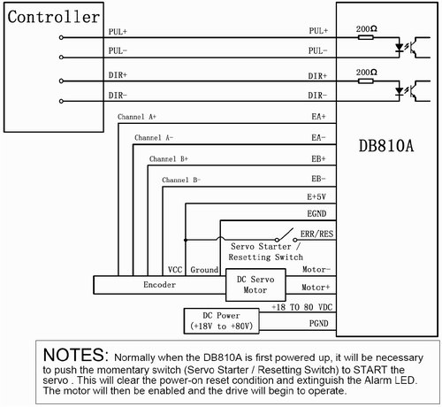
Figure 6:
Typical connection (Differential control signal and
differential encoder.)
|
Click here
for more information about DB810A.
|