Sales
Contact Sales
Contact |
|
|
| Tech Support Contact
|
|
| |
|
|
|

|
|
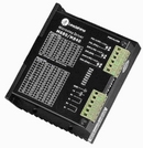
| M880/M840
Microstepping Driver |
|
|
Features |
-
High performance, low
cost
-
Supply voltage up to
+90VDC
-
M880
output current up to 7.8A
-
M840
output current up to 3.9A
-
Inaudible 20khz chopping
frequency
-
TTL
compatible and optically isolated input
signals
-
Automatic idle-current
reduction
-
Mixed-decay current control for less
motor heating
-
14
selectable resolutions up to 50,000
steps/rev
-
Suitable for 2-phase and 4-phase stepping
motors
-
Over-current, over-voltage
protection
-
Small
size (M880:119 x 97 x 48 , M840:119 x 97 x 31
) | |
| Introduction |
|
M880/M840 are
high performance microstepping drivers based on one of
the most advanced technologies in the world today. They
are suitable for driving any 2-phase and 4-phase hybrid
step motors. By using advanced bipolar constant-current
chopping technique, they can output more speed and power
from the same motor, compared with traditional
technologies such as L/R drivers. Its 3-state current
control technology allows coil current to be well
controlled, with relatively small current ripple and
results in less motor heating. |
| Applications |
|
Suitable for
a wide range of stepping motors of size Nema 34 and 43,
and usable for various kinds of machines, such as X-Y
tables, labeling machines, laser cutters, engraving
machines, and pick-place devices. Extremely suitible for
applications expected to be low vibration, high speed
and high precision. |
| Electric Specifications
(Tj=25¡æ) |
Parameters |
M880/M840 |
|
Min. |
Typical |
Max. |
Unit |
|
Peak
Output Current |
2.8,/1.4 |
- |
7.8,/3.9 |
Amps |
|
Supply
voltage |
+24 |
+68 |
+90 |
VDC |
|
Logic
signal current |
7 |
10 |
16 |
mA |
|
Pulse
input frequency |
0 |
- |
300 |
Khz |
|
Isolation resistance |
500 |
- |
- |
M¦¸ | |
|
Mechanical
Specifications (Unit: mm, 1 inch=25.4
mm) |
|
|
| Pin Assignment and Description
|
Control
Signal Connector P1 pins
|
Pin
Function |
Details |
PUL©€(+5V) |
Pulse
signal: in single pulse(PUL/DIR) mode, this input
represents pulse signal, effective for each
upward-rising edge; in double pulse mode (CW/CCW)
this input represents clockwise(CW)pulse. For
reliable response, pulse width should be longer
than 3us. |
|
PUL-
(PUL) |
DIR+
(+5V) |
DIR
signal: in PUL/DIR mode, this signal has low/high
voltage levels, representing two directions of
motor rotation; in CW/CCW mode (set by inside
jumper JPI), this signal is counter-clock (CCW)
pulse, effective on each rising edge. For reliable
motion response, direction signal should be sent
to driver 5us before the first pulse of a motion
direction reversal. |
|
DIR-
(DIR) |
|
ENA+
(+5V) |
Enable
signal: This signal is used for enabling/disabling
the driver. High level (NPN control signal, PNP
and Differential control signals are on the
contrary, namely Low level for enabling.) for
enabling the driver and low level for disabling
the driver. Usually left UNCONNECTED
(ENABLED). |
|
ENA-
(ENA) |
Power
connector P2 pins
|
Pin
Funtion |
Details |
|
Gnd |
DC power ground |
|
+V |
DC power supply, +18VDC £ +80VDC,
Including voltage fluctuation and EMF
voltage. |
|
Phase
A |
Motor coil A (leads A+ and
A-) |
Phase
B |
Motor coil B (leads B+ and
B-) | |
| Microstep Resolution
Selection |
|
Microstep resolution is set by SW5, 6, 7, 8 of
the DIP switch as shown in the following
table:
|
Microstep |
ustep/rev.(for
1.8¡ãmotor) |
SW5 |
SW6 |
SW7 |
SW8 |
|
2 |
400 |
on |
on |
on |
on |
|
4 |
800 |
on |
off |
on |
on |
|
8 |
1600 |
on |
on |
off |
on |
|
16 |
3200 |
on |
off |
off |
on |
|
32 |
6400 |
on |
on |
on |
off |
|
64 |
12800 |
on |
off |
on |
off |
|
128 |
25600 |
on |
on |
off |
off |
|
256 |
51200 |
on |
off |
off |
off |
|
5 |
1000 |
off |
on |
on |
on |
|
10 |
2000 |
off |
off |
on |
on |
|
25 |
5000 |
off |
on |
off |
on |
|
50 |
10000 |
off |
off |
off |
on |
|
125 |
25000 |
off |
on |
on |
off |
|
250 |
50000 |
off |
off |
on |
off | |
| Current Setting |
|
Current
for M840 |
Current
for M880 |
SW1 |
SW2 |
SW3 |
|
1.4A |
2.8A |
on |
on |
on |
|
1.8A |
3.5A |
off |
on |
on |
|
2.1A |
4.2A |
on |
off |
on |
|
2.5A |
4.9A |
off |
off |
on |
|
2.9A |
5.7A |
on |
on |
off |
|
3.2A |
6.4A |
off |
on |
off |
|
3.5A |
7.0A |
on |
off |
off |
|
3.9A |
7.8A |
off |
off |
off | |
| Typical Connections |

Figure 2:
Typical connections |
|
| | |
|
|
|
 | |