|
|
|
|||||||||||||||||||||||||||||||||||||||||||||||||||||||
|
|||||||||||||||||||||||||||||||||||||||||||||||||||||||
|
Reading over the various potential modifications, I decided the DC motor needed to come fairly early in the process for several reasons. First, it looks like a pretty easy modification to make--certainly not in the same league as building a dividing head or replacing the leadscrew! Second, there is a lot of bang for the buck. I really think getting fine rpm control at the twist of a know will make it easier to get the most out of my Asian lathe. Having now completed the modification, I have to say that it is fabulous! Being able to change speed at the twist of the dial is a dream come true. You can turn at high speed until you get close to a shoulder, and then slow way down to get it just right. If chatter sets in, change speeds and it goes away. Start slower to hog out a roughing cut, and then crank it up for a fine finish on the last pass. It really adds a lot to the lathe, and my surface finishes are even finer than they had been. Highly recommended! Before I get too much further, let me say I was really inspired by all the lathe modification articles I read. I didn't invent this mod, I've largely copied the work of others. Be sure to read their web articles too and you'll learn a lot. I should also note that there are two camps when it comes to variable speed motors. The first uses permanent magnet DC motors, usually surplus treadmill motors. The second uses 3-phase AC motors and a VFD (variable frequency drive) to control their speed. It's fair to say the latter is closer to industry practice. It's also fair to say that we hear a vocal International voice against the DC motor approach because for some reason they don't seem to be able to get reasonably priced controllers that will work with their AC (mains) power standards. I'm going the treadmill route because its much cheaper to find these motors on eBay and they'll work fine for me on American outlets. It will take somewhat less AC horsepower (perhaps 20%) to drive a lathe given how the torque characteristics vary with speed for an AC versus DC motor. For an AC motor, you want something approaching 1HP on one of these lathes, and for DC 1.2 would be ideal. Note that while my motor is rated at "2.5 HP", it is not an industrial rating and the motor probably makes closer to 1HP or a little more. Also note the speed range on the motor you're looking at. Most of these lathes get down close to 1:1 (usually 1:1.2) on their pulley arrangements. Figure your max desired spindle rpm and divide it by 1.2 for a decent estimate of what maximum speed you'll need from your motor. This is a pretty cheap mod when you buy the parts from surplus or eBay. Take a look at what I'm using:
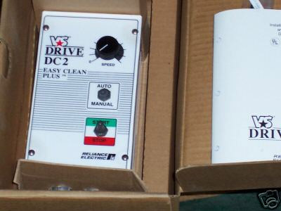
Reliable Electric DC-2 Variable Speed Motor Controller.
1/2-2HP. 90-180V 10A. Model #DC-92U. New, unused, with manual. There are plenty of DC controllers available on eBay. I did a search on "(variable, controller, controler) motor" and bid on this one. Check the specs to be sure they're compatible with your motor. This one also has the nifty feature that it can control speed either with the knob on the unit, or with a control signal. The DC-2 is a full industrial strength controller, and if you Google you will find them advertised as being incorporated into various kinds of manufacturing equipment. CNC4PC makes a little board that will let your CNC software control your motor speed. How cool is that? Not sure I'll ever take advantage of it. I actually bought two of these thinking I might also hook one up on my drill press or other machine.
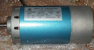
New 2.5 HP 130VDC 10A 4500RPM CW rotation Treadmill
Replacement Motor. This is a permanent magnet continuous duty motor. DC motors are also easy to find on eBay. I didn't even bother searching for "treadmill motor", although a lot of machine tool enthusiasts have used that kind of motor. You want something with this kind of horsepower and voltage ratings. Go through until you find a winner. Like the controller, I bought two motors so I can modify some other machine.
This modification requires the following steps: 1. Interface the DC Controller to the DC Motor. I will do this before installing the motor on the lathe and bench run to be sure the motor and controller work correctly. 2. Fabricate a mounting bracket to attach the motor to the lathe. 3. Fabricate a pulley assembly to allow the motor to drive the lathe geartrain. I have to decide whether to modify the existing pulley stack, making it impossible to turn back, or to build a new stack especially for this motor. Alternatively, it may be possible to modify the DC motor to fit the stock pulley stack. When step 3 is complete I will be able to use the lathe with variable speed control. 4. Fabricate a custom control panel to fit the lathe.
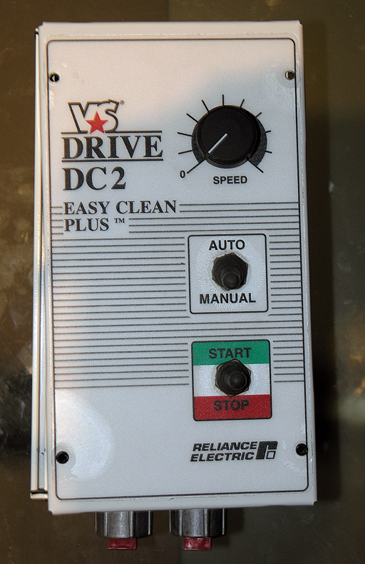
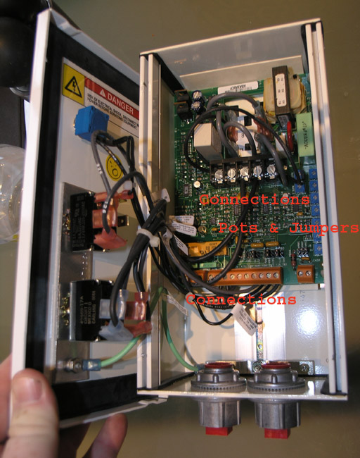
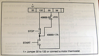
Front panel about to be removed... Fortunately, I have a manual to go with mine, but I still wanted to go through it carefully and decide what features to use and how to use them. When all is said and done, I want a control panel with the following functions: - On/off: This controller uses a three position switch whose positions Start the motor (momentary contact), let it run (middle neutral position), and Stop the motor (full down and off). - Speed Dial: A continuously variable potentiometer. - Jog: A momentary contact that just bumps the spindle while held down. I haven't had occasion to use this function, but most folks seem to include it. - Reverse: A switch to reverse the contacts so the motor runs in reverse. Note: Some controls have a fancy electronically braked version of this. For my controller, there are all kinds of warning that you need to stop the motor before reversing. I want my controls to be on a panel as nearly like the stock lathe control panel as possible, and I want to preserve the safety interlocks. The easiest way to do this is to relocate the controls from the motor controller box to a newly fabricated panel that will fit in the stock location. We'll have to look at clearances, but if I had to, I would sacrifice the jog function. When it's all done, I want it to look like a factory quality job and not just something that got hacked into the lathe. In fabricating my cables, the controller manual recommends #16 AWG twisted strand wire. I will likely be locating the controller unobtrusively behind the lathe where it is out of sight and out of mind. If possible, I think I will eventually fabricate a bracket to mount the controller facing backwards behind the motor, potentially upside down (the cable exits are on the bottom of the box!). The same bracket will be set up to eventually accomodate a DRO. Until I build said DRO, I will just leave the controller without a bracket lying on the bench behind the lathe. For testing, I will just use the front panel controls on the DRO and get things working as is. This way I can use the lathe to machine the pulley to fit the motor.
DC-2 Innards... Let's review the internal connections on the DC-2. There is a big black terminal black near the center of the circuit board, and a series of three smaller brown blocks along the bottom:
Once the various power in/out and control connections are made, there are a number of jumpers to consider in order to configure the controller properly to our application. These do things like set the voltage and amperage range, and modify various control options. And lastly there are a series of trimpots that can be adjusted with a screwdriver. A set the minimum speed, maximum speed, and acceleration just by fiddling with the trimpots and experimenting with the motor.
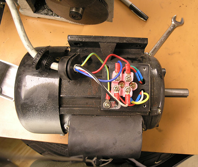
In case I ever need to put the AC Motor back, here are the connections...
AC Power Cord: I cut the female end off of a spare computer power cord I had, ran it into the bottom of the controller box, tied a knot in the cord for strain relief (would hate to pull the terminals lose and have live AC current bouncing around inside that case!), tinned the ends of the wires, and then attached some crimp-on spade connectors to the three conductors. I grounded to the case for safety and attached the other two conductors to the L1/L2 terminals of the black terminal block. DC Motor Connection: I used some lamp cord to make sure I had wire with decent current carrying capacity, soldered some spades on either end, tied a strain relief knot inside the controller box, and voila! I was connected. Test Run: Considering I did buy these components on eBay, it only made sense to test them early in this project before I had invested a lot of time in them. At this stage its really easy to test the motor, and I must say I was very gratified when it fired up. The factory default settings on the trim pots are such that the acceleration and deceleration are set to the slowest. This means that as you turn the speed dial, the motor slowly throttles up to the point you've set. I tweaked the pots a bit to make it slightly more responsive. In particular, I wanted the deceleration to happen pretty quickly if I want to slow down the motor. I also fiddled with the minimum and maximum speeds. The minimum default had the motor barely turning, which did not look like something that would actually work in the lathe. I dialed it up to 30 or 40 rpm at the minimum. Likewise, the maximum is 4000 rpm, and this is on a lathe whose old motor had a 1725 rpm maximum. 4000 seemed a bit much, so I scaled that back a bit too. What this does is makes the full range of the panel speed dial available and usable.
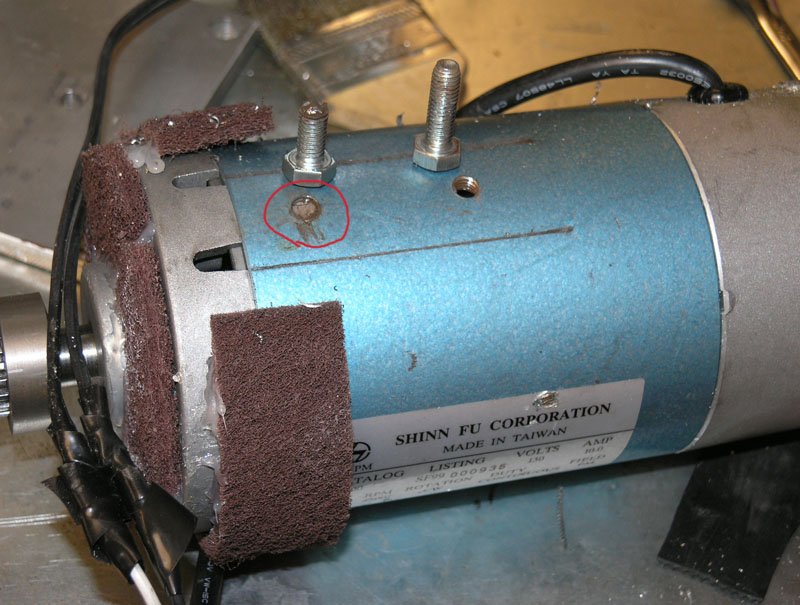
This was a straightforward task involving some aluminum stock, my horizontal bandsaw, my drill press, and trips to the hardware store to purchase appropriately sized nuts, bolts, and washers. Remove Factory Motor and Measure: Now is the chance to measure the factory motor, both for its mountings and for the pulley and shaft dimensions that will need to be matched. Fabricate Mounting Bracket: I had some 1/4" thick aluminum plate together with some 3/16" that I used to fabricate a motor brack. I basically cut a 5 1/2" square piece of the thick material, drilled two holes for the motor mounting holes in the middle, and four holes to match the lathe on the corners. I then took the thinner material and made a couple of side plates that are held on by the corner holes in the big plate at top and bottom. This was quick and easy. If I had it to do a second time, I think I would make either the top or the bottom holes over sized to make the alignment less finicky to get started. You can see what it looks like (partially at least) down below. Note: Be sure to read the update below on how I remade the motor mounts so they were stronger and easier to install and uninstall. Fabricate Dust Cover: Here I followed the Cletus Berkeley patented method of hot gluing scrub pads over the motor's cooling holes to keep out the swarf. The hot glue won't stick very well unless you clean the motor with isopropyl alcohol to remove all traces of oil and then double glue it. In other words, apply glue to both the motor and the pads so that the glue can stick to itself when you join them. You can see what it looks like down below.
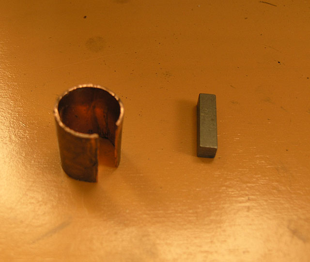
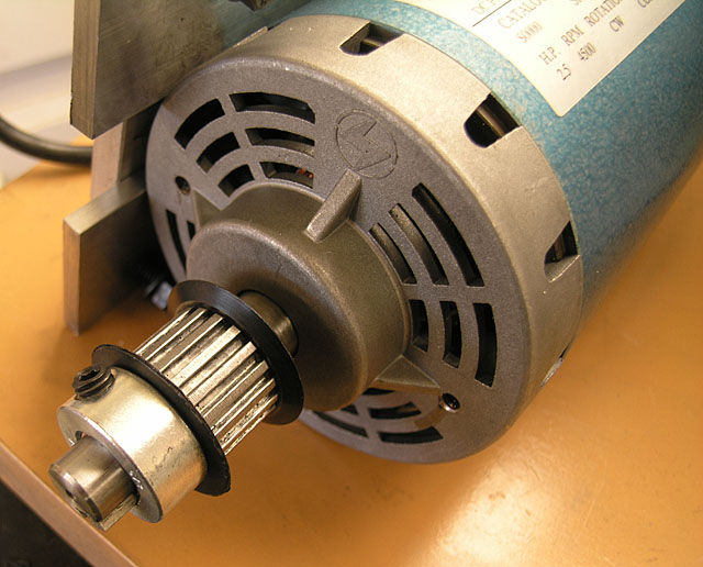
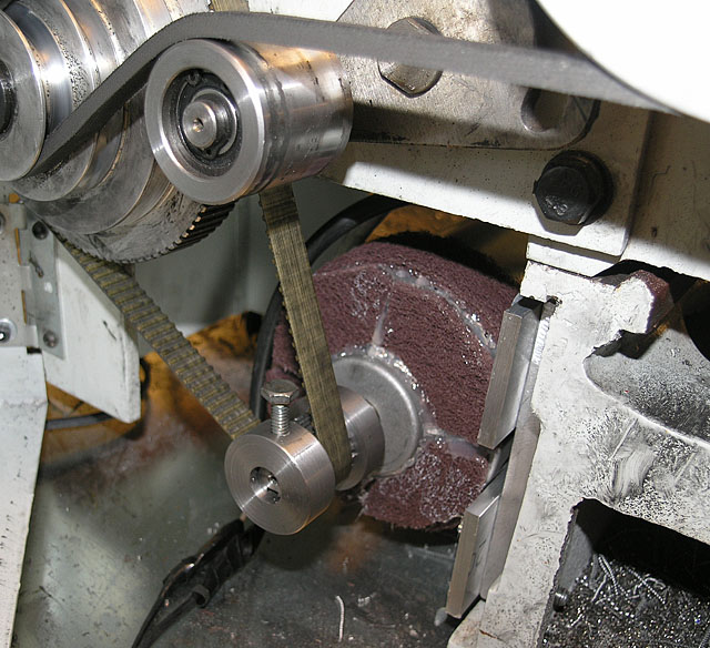
This was slightly touchy. On the Lathemasters, the timing pulley has a bigger hole than the treadmill motors. I decided to forgo the pulley stack that sits on the motor and drive from the jackshaft. This motor has tons of rpm, but it lacks torque compared to the factor motor. The jackshaft gives it a 2:1 ratio to help that out. That meant I only had to mount the timing pulley. I decided to sleeve the timing pulley with some copper pipe I had sitting around so it would be more nearly concentric on the shaft:
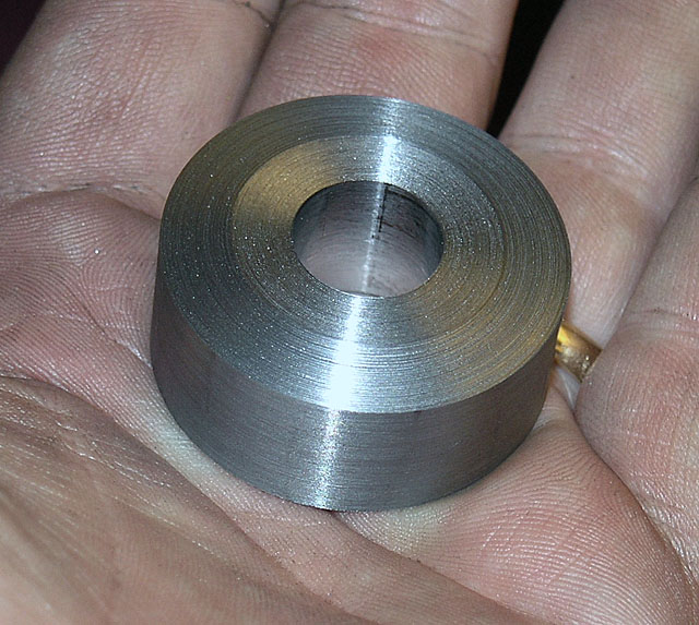
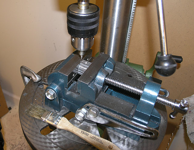
Sleeve and shortened key... I also shortened the key so it only runs under the timing pulley. Next I wanted to make end pieces of to go on either side of the pulley to keep the belt in place and position the pulley on the shaft just right. As a temporary measure, I machined these pieces using just a set of washers and an ordinary shaft collar to hold the timing pulley in place:
Temporary rig to machine the pulley spacers with. You can also see the mounting plates... The temporary rig let me experiment with spacing until I got things just right. Certain configurations seemed to make the belt want to walk off the end. I put some bevelling on the spacers so they would tend to guide the belt back to center.
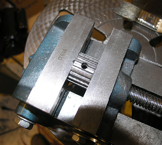
Spacer with beveling... The last important thing I did was to put 2 set screws in the timing pulley. I put these at 90 degrees to one another. Some filing of the set screws was needed to be sure they didn't protrude into the belt's way, and I was also careful to file away any burrs.
Center drilling for the pulley set screw. You do center drill all of your holes, don't you?
Drilled with a #7 prior to tapping the 1/4-20 threads with my piloted tap...
Finished motor with machined pulley spacers and dust covers... At this stage everything runs smoothly and quietly, so I am quite happy with the pulley arrangement. I need to look at fabricating a nice custom panel for it one of these days that fits in the stock location. For now I just want to put a few miles on it to be sure it works well. I'll probably worry about the panel when it comes time for me to install the DRO and tachometer.
Okay, who has been running my lathe backwards! Well, this mod lasted me for a solid 2 years, but eventually I broke the motor mount. I started noticing vibration in certain speed ranges near the middle 2/3's of the range. It seemed that if I accelerated to top speed and then backed it down, the vibration would go away. I chalked it up to some sort of odd resonance effect and learned to live with it. Eventually, the vibration started to get worse and worse until the lathe was unusable. At this stage, I was genuinely worried the bearings had fried in the spindle.
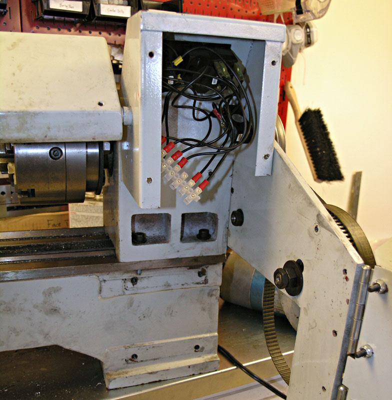
There's a lot to clear away to get at the motor mounts very easily... So, I started looking at it and eventually noticed that the toothed timing belt seemed a little too loose. Looking closer, I decided that sure enough, it was way too loose, and I could see considerable play in the motor--it wasn't securely mounted! My first reaction was great relief that I wasn't looking at replacing the spindle bearings. My second was a touch of annoyance. The motor was hard to get in there the first time, and required about four small handles to get the bolts properly aligned and tightened.
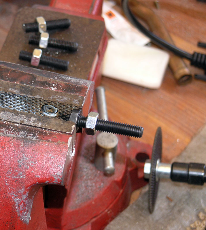
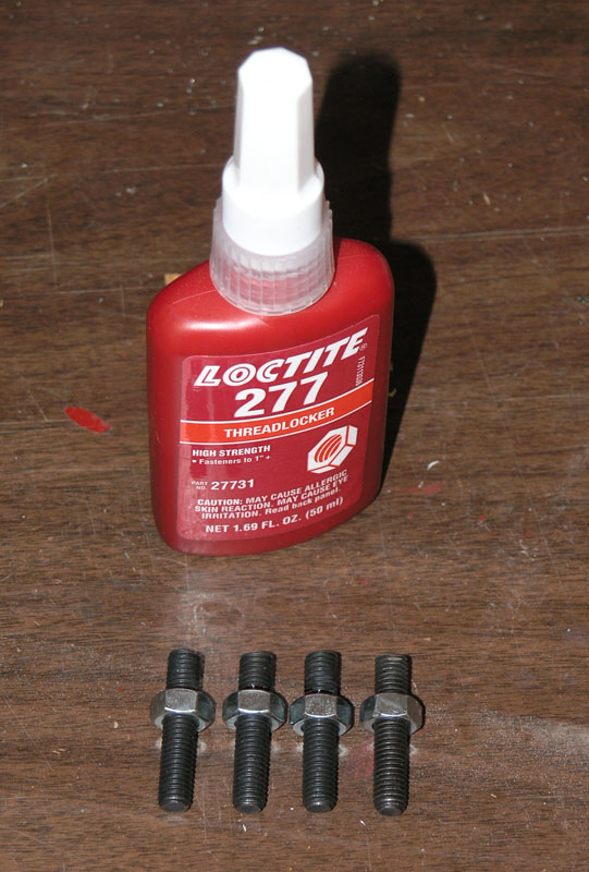
Broken mounting bolt. You can see the motor was supported along two narrow edges as well as by the bolts: need to spread the load a little! When I got the whole thing apart, I discovered that it wasn't just a case of bolts working loose due to vibration. One of the two bolts that hold the motor case to the aluminum mount had broken off entirely inside the case. Aha, says I! I'm going to need to make a better motor mount so this doesn't happen again. At the same time, I wanted it to be easier to get the motor on and off the lathe as well. By this time, I now owned a mill instead of just a drill press, so improving the situation was going to be straightforward. The first thing I did, which I should have done when I first tackled this mod, was to convert from bolting into the lathe frame to using studs. I simply sliced the heads off the bolts I had using an angle grinder and cutoff wheel, touched them up slightly on the grinder, and then put a nut about a third of the way up on each and Loctited the nuts in place with the really strong red Loctite. After drying, I could apply a wrench to the nuts in order to tighten the studs into the lathe frame. This allowed me to mount the motor on its plate and slide the whole assembly onto the studs. Much easier to install the motor now!
To make a stud, first cut the head off...
Then Loctite the nuts so you have a way to tighten the stud...
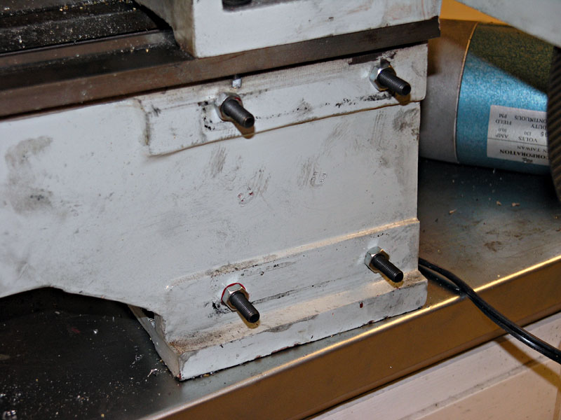
Studs make it easier to drop the motor on its mounting plate into place... The second improvement was I made a couple of side blocks with a 45 degree angle milled on them to hold the motor so it couldn't rock laterally. I think such rocking is likely how the original motor mount got broken. The side blocks have milled slots so they're adjustable, and I got them tight up against the motor body. I bolted the whole assembly back together and it runs smooth as silk! Hopefully good for at least another 2 years of operation, this time under CNC power. |
|||||||||||||||||||||||||||||||||||||||||||||||||||||||
|
|
|
|
|
Resources |
Workshop
|
|||||||||||||||||||||||||||||||||||||||||||||||||
 |
|
||||||||||||||||||||||||||||||||||||||||||||||||||||||